Epson Stylus Pro 4900/Epson Stylus Pro 4910 Revision A
DISASSEMBLY & ASSEMBLY Disassembly and Assembly Procedure 214
Confidential
3.4.6.7 Paper Cassette Sensor
1. Remove the Front Cover. (p142)
2. Remove the Right Upper Cover. (p138)
3. Remove the Control Panel Cover. (p136)
4. Remove the Right Cover. (p139)
5. Remove the Left Cover. (p137)
6. Remove the Media Eject Cover. (p148)
7. Remove the Left IC Cover Frame. (p140)
8. Remove the Full (Left) Side Cartridge Holder. (p242)
9. Remove the Power Supply Box. (p157)
10. Remove the lower cover. (Step 11 in “3.4.6.6 Paper Empty Sensor” (P. 211))
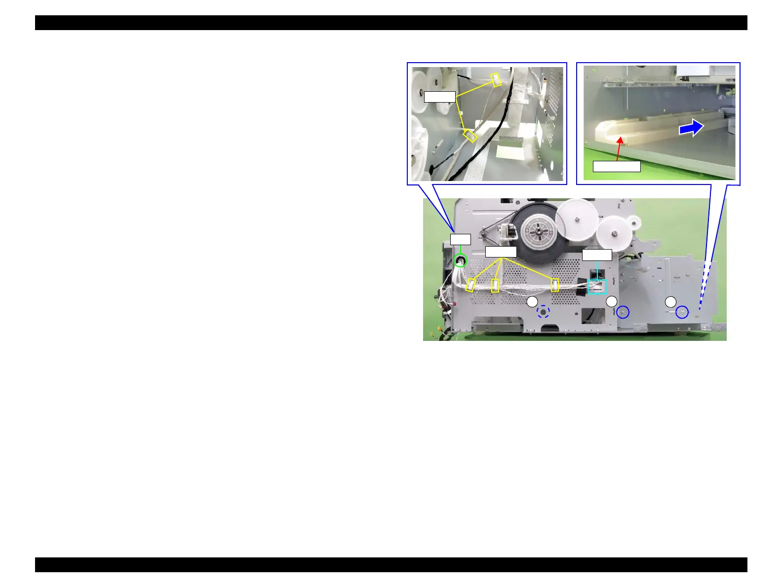
11. Release the harnesses from the five clamps and the saddle.
12. Pull out the harnesses from the hole of the frame.
13. Remove the three screws that secure the cassette rail.
A) Silver, Phillips, Bind P-tite M3x8: three pieces
14. Slide the cassette rail to the rear to remove it.
Figure 3-141. Removing the cassette rail
A
A
A
Clamps
Saddle
Hole
Clamps
Cassette rail
 Loading...


