Epson Stylus Pro 4900/Epson Stylus Pro 4910 Revision A
DISASSEMBLY & ASSEMBLY Disassembly and Assembly Procedure 156
Confidential
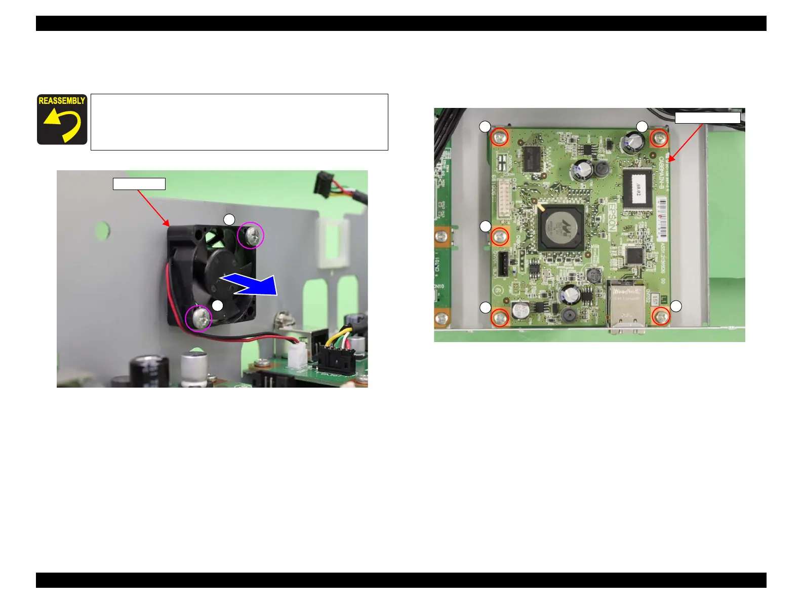
5. Remove the two screws that secure the Cooling Fan, and remove the Cooling Fan.
A) Silver, Phillips, Bind machine screw M3x14: two pieces
Figure 3-59. Removing the Cooling Fan
6. Remove the five screws that secure the Network Board, and remove the Network
Board.
B) Silver, Phillips, Bind machine screw M3x6: five pieces
Figure 3-60. Removing the Network Board
When installing the Cooling Fan, be careful of the installation
direction referring to Figure 3-59.
A
A
Cooling Fan
B
B
B
B
B
Network Board
 Loading...


