Epson Stylus Pro 4900/Epson Stylus Pro 4910 Revision A
DISASSEMBLY & ASSEMBLY Disassembly and Assembly Procedure 188
Confidential
3.4.5.6 PE Sensor
1. Remove the Front Cover. (p142)
2. Remove the Right Upper Cover. (p138)
3. Remove the Control Panel Cover. (p136)
4. Remove the Right Cover. (p139)
5. Remove the Mid-Right Cover/Mid-Left Cover. (p150)
6. Remove the Rear Cover. (p144)
7. Remove the Rear Unit. (p145)
8. Remove the Printer Cover. (p133)
9. Remove the upper rear cover. (Step 7 in “3.4.5.9 Paper Thickness Sensor1, 2” (P.
195))
10. Remove the Release Assy. (Step 4 to Step 7 in “3.4.5.10 Release Motor Assy” (P.
197))
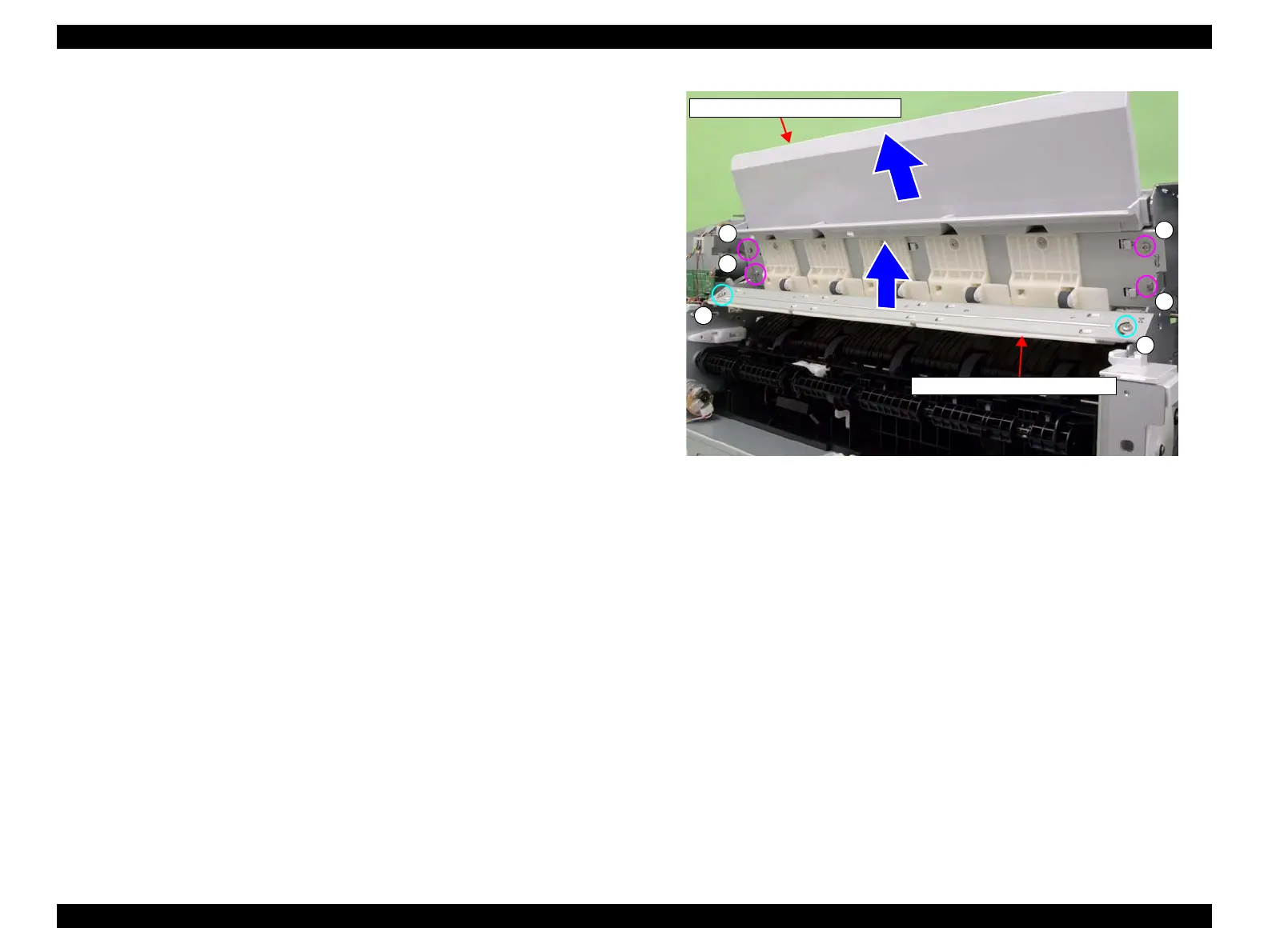
11. Remove the four screws that secure the “PAPER GUIDE,MANUAL FEED”.
A) Silver, Phillips, Bind machine screw M3x6: four pieces
12. Remove the “PAPER GUIDE,MANUAL FEED”.
13. Remove the two screws that secure the “PAPER GUIDE,ROLL,UNDER”.
B) Silver, Phillips, Bind machine screw M3x6: two pieces
14. Remove the “PAPER GUIDE,ROLL,UNDER”.
Figure 3-101. Removing the “PAPER GUIDE,ROLL,UNDER”
“PAPER GUIDE,MANUAL FEED”
A
A
A
A
B
B
“PAPER GUIDE,ROLL,UNDER”
 Loading...


