Epson Stylus Pro 4900/Epson Stylus Pro 4910 Revision A
DISASSEMBLY & ASSEMBLY Disassembly and Assembly Procedure 141
Confidential
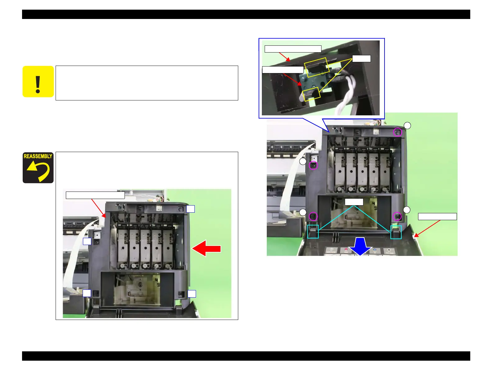
3. Remove the four screws that secure the Right IC Cover Frame, and remove the
Right IC Cover Frame.
A) Silver, Phillips, Bind P-tite M3x8: four pieces
4. Widen the gap between the hooks that secure the Right IC Sensor, and remove the
Right IC Sensor from the Right IC Cover Frame.
5. Pull down the Right IC Cover to disengage the joints, and remove the Right IC
Cover.
Figure 3-39. Removing the Right IC Cover Frame
C A U T I O N
Remove the IC Sensor in the following steps, release the lower hook
(the narrow one) so as not to damage the hooks.
When installing the IC Cover Frame, tighten the screws in the
order given in the figure below.
When installing the Right IC Cover Frame, attach it to the
main frame while pressing it in the direction of the arrow.
1
2
3
4
Right IC Cover Frame
Joints
Right IC Cover
A
A
A
A
Right IC Sensor
Hooks
Right IC Cover Frame
 Loading...


