Epson Stylus Pro 4900/Epson Stylus Pro 4910 Revision A
DISASSEMBLY & ASSEMBLY Disassembly and Assembly Procedure 249
Confidential
3.4.9.11 Head FFC
1. Remove the Front Cover. (p142)
2. Remove the Control Panel Cover. (p136)
3. Remove the Right Upper Cover. (p138)
4. Remove the Right Cover. (p139)
5. Remove the Left Cover. (p137)
6. Remove the upper front cover.
(Step 6 to Step 10 in “3.4.2.2 Printer Cover Sensor” (P. 134))
7. Unlock the carriage, and move the CR Unit to the left end. (p124)
8. Remove the CR Cover. (p149)
9. Remove the Rear Cover. (p144)
10. Pull out the Board Tray. (Step 3 to Step 5 in “3.4.2.13 Board Tray” (P. 147))
11. Remove the Ink Selector Assy from the CR Unit. (Step 9 to Step 14 in “3.4.9.1 Ink
Selector Assy” (P. 229))
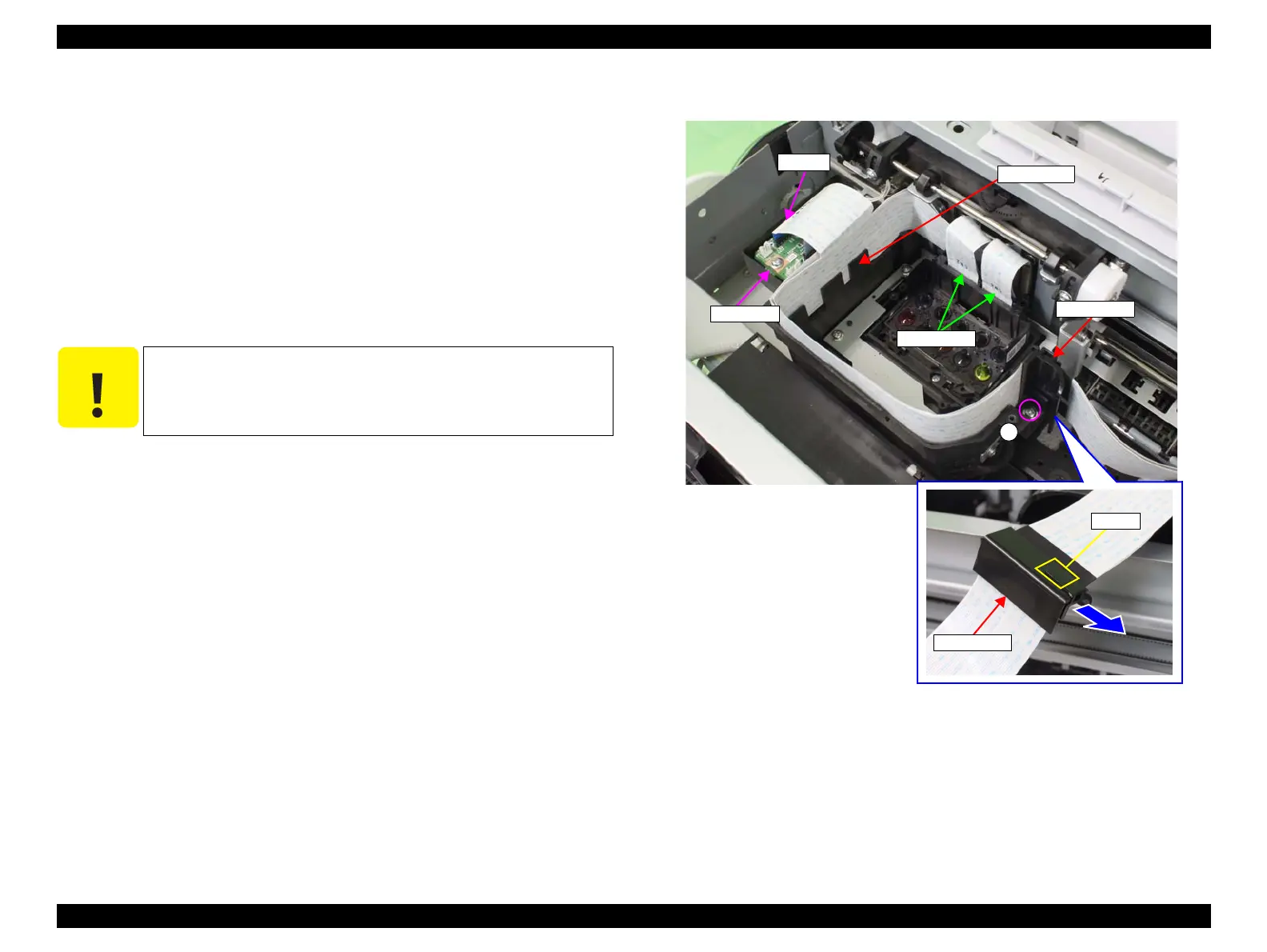
12. Disconnect the Head FFC from the Printhead.
13. Disconnect the Head FFC (CN100) from the SUB Board.
14. Remove the screw that secures the FFC holder.
A) Silver, Phillips, Round Washer Head P-tite M3x8: one piece
15. Disengage the hook of the FFC holder to release the FFC holder, and remove the
FFC holder from the Head FFC.
16. Release the Head FFC from the cable guide provided inside the CR Unit.
Figure 3-184. Disconnecting the Head FFC
C A U T I O N
Be sure to move the CR Unit to the left end before performing the
following steps. Performing the following step with the CR on the
platen may damage the Printhead.
FFC holder
A
CN100
Hook
FFC holder
SUB Board
Cable guide
Head FFC
 Loading...


