Epson Stylus Pro 4900/Epson Stylus Pro 4910 Revision A
DISASSEMBLY & ASSEMBLY Disassembly Flowchart 116
Confidential
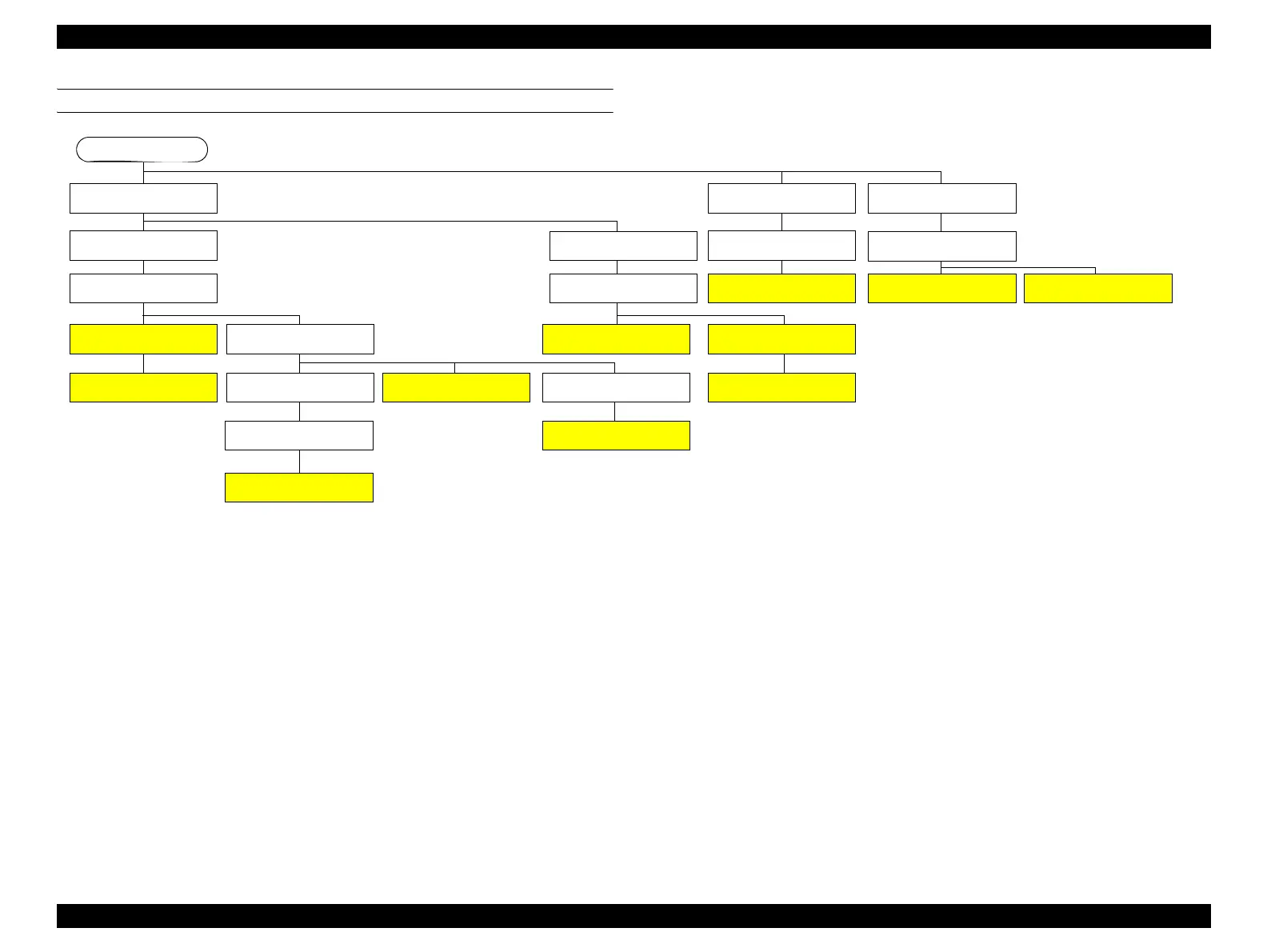
ELECTRIC CIRCUIT COMPONENTS
Start
See “3.4.2.8 Front Cover (p142)”
See “3.4.2.3 Control Panel Cover
(p136)”
See “3.4.2.6 Right Cover (p139)”
See “3.4.2.5 Right Upper Cover
(p138)”
See “3.4.3.10 LED Board (p166)”
See “3.4.2.11 Rear Unit (p145)”
See “3.4.3.7 SUB-C Board (p163)”
See “3.4.3.3 Power Supply Box
(p157)”
See “3.4.3.4 Power Supply Board
(p159)”
See “3.4.3.11 Control Panel Board
(p167)”
See “3.4.3.1 Main Board (p152)”
See “3.4.3.2 Network Board
(p155)”
See “3.4.1.2 Roll Unit (p125)”
See “3.4.2.17 Left Roll Cover/
Right Roll Cover (p151)”
See “3.4.3.8 SUB-D Board
(p164)”
See “3.4.2.15 CR Cover (p149)”
See “3.4.2.10 Rear Cover (p144)”
See “3.4.3.5 SUB Board (p161)”
See “3.4.3.6 SUB-B Board (p162)”
See “3.4.2.16 Mid-Right Cover/
Mid-Left Cover (p150)” (R only)
See “3.4.2.10 Rear Cover (p144)”
See “3.4.3.9 AID Board (p165)”
See “3.4.2.10 Rear Cover (p144)”
See “3.4.2.4 Left Cover (p137)”
 Loading...


