Epson Stylus Pro 4900/Epson Stylus Pro 4910 Revision A
DISASSEMBLY & ASSEMBLY Disassembly and Assembly Procedure 152
Confidential
3.4.3 Electric Circuit Components
3.4.3.1 Main Board
1. Remove the Rear Unit. (p145)
2. Remove the Rear Cover. (p144)
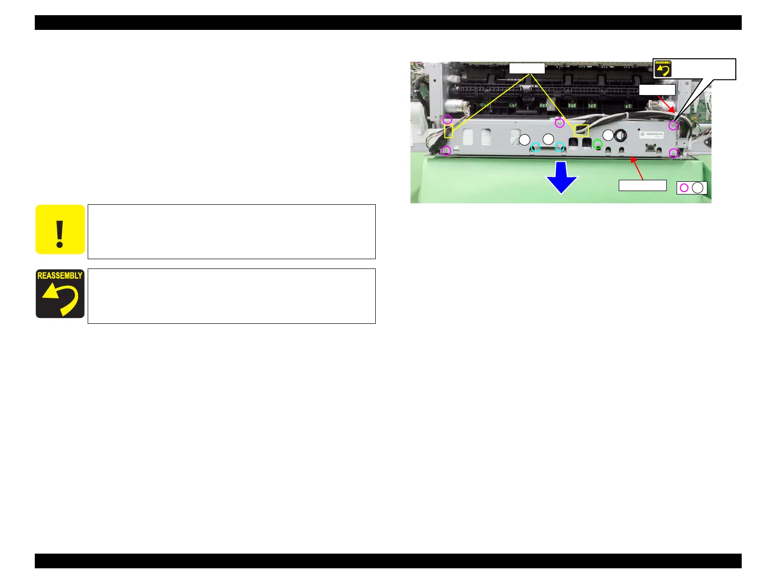
3. Remove the eight screws, and pull out the Board Tray slightly.
A) Silver, Phillips, Round Washer Head S-tite M3x8: five pieces
B) Silver, M3 hex screws: two pieces
C) Silver, Phillips, Bind machine screw M3x6: one piece
4. Pull out the Board Tray slightly.
5. Release the harness from the two saddles.
Figure 3-55. Pulling out the Board Tray
C A U T I O N
The Main Board and Network Board are stored in the Board Tray
and they are connected to the harnesses from the main body.
Therefore, be careful not to pull out the Board Tray too far from
the main body in the next step.
Secure the cable tie and the plate with the same screw shown in the
figure.
B
B
C
A
Saddles
Cable tie
Board Tray
Screw together
 Loading...


