Epson Stylus Pro 4900/Epson Stylus Pro 4910 Revision A
DISASSEMBLY & ASSEMBLY Disassembly and Assembly Procedure 165
Confidential
3.4.3.9 AID Board
1. Remove the Front Cover. (p142)
2. Remove the Right Upper Cover. (p138)
3. Remove the Control Panel Cover. (p136)
4. Remove the Right Cover. (p139)
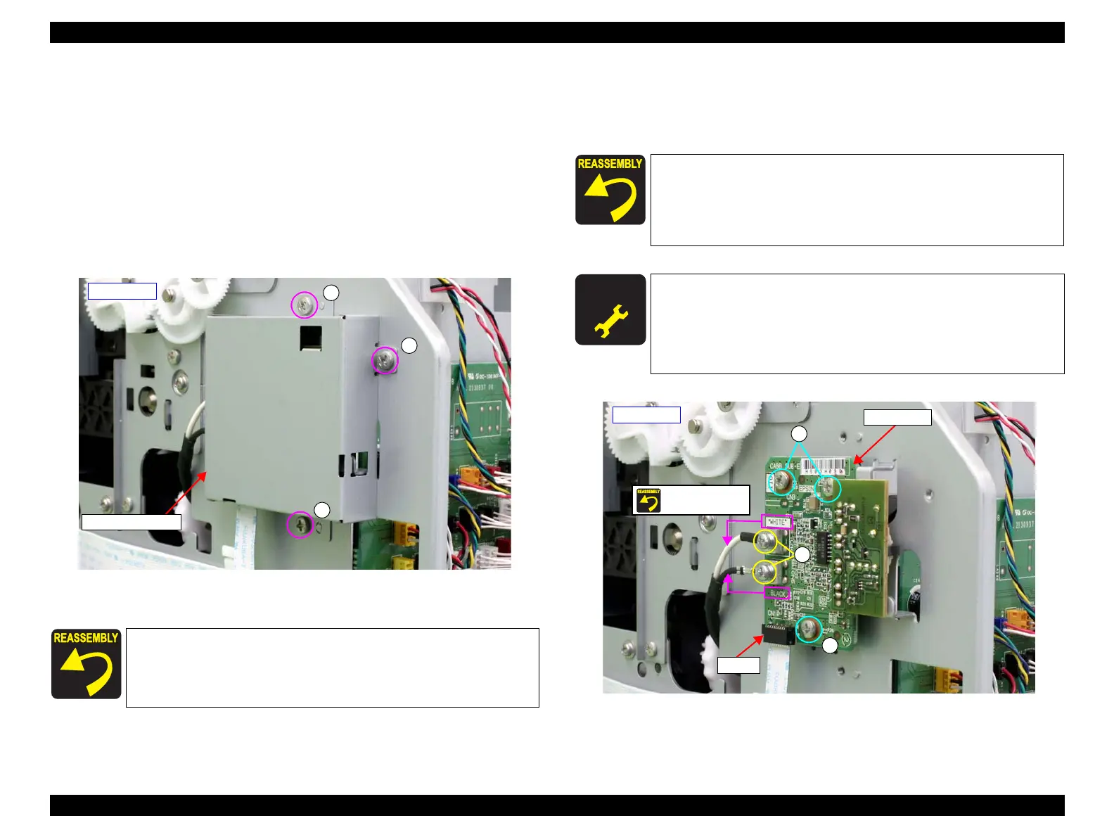
5. Remove the three screws that secure the AID Board Cover, and remove the AID
Board Cover.
A) Silver, Phillips, Bind machine screw M3x6: three pieces
Figure 3-73. Removing the AID Board Cover
6. Disconnect the FFC on the AID Board.
7. Remove the five screws that secure the AID Board, and remove the AID Board.
B) Silver, Phillips, Bind S-tite with S.W & P.W. M3x6: two pieces
C) Silver, Phillips, Bind machine screw M3x6: three pieces
Figure 3-74. Removing the AID Board
When installing the AID Board, be sure to refer to Chapter 6
“Appendix” (see p432) and connect the connectors correctly.
AID Board Cover
- Left side -
A
A
A
Secure the terminal of the AID Board and the AID Board with
the same screw B. At this point, make sure to match the color
(WHITE/BLACK) of the cable with the color written on the
board.
Make sure to secure the screw B tightly.
A D J U S T M E N T
R E Q U I R E D
Be sure to refer to Chapter 4 “Adjustment” (see p277) and perform
specified adjustments after replacing the AID Board.
<Adjustment items>
1. Nozzle Check
2. AID Function Check
- Left side -
Screw together
B
C
C
FFC
AID Board
 Loading...


