Epson Stylus Pro 4900/Epson Stylus Pro 4910 Revision A
DISASSEMBLY & ASSEMBLY Disassembly and Assembly Procedure 135
Confidential
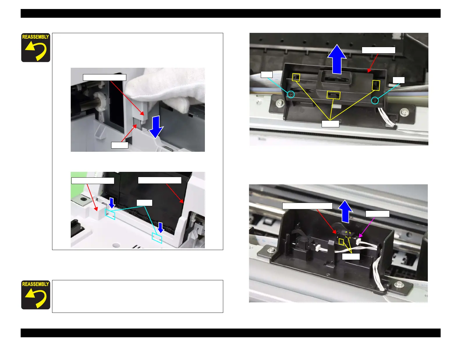
11. Disengage the three hooks that secure the Sensor Cover, and remove the Sensor
Cover.
Figure 3-31. Removing the Sensor Cover
12. Disengage the hooks that secure the Printer Cover Sensor, and remove the Printer
Cover Sensor.
13. Disconnect the connector from the Printer Cover Sensor.
Figure 3-32. Removing the Printer Cover Sensor
When installing the upper front cover, be careful of the following.
First attach the cover into the cut on the right of the main
frame, then reassemble the cover in the reverse order of the
disassembling procedure.
Make sure to insert the ribs on the upper front cover into the
holes on the Media Eject Cover.
When installing the Sensor Cover, be sure to set the positioning
holes of the sensor cover to the bosses of the sensor holder.
Cut
Upper front cover
Media Eject Cover
Ribs
Upper front cover
Sensor Cover
Hooks
Boss
Boss
Printer Cover Sensor
Connector
Hooks
 Loading...


