Epson Stylus Pro 4900/Epson Stylus Pro 4910 Revision A
DISASSEMBLY & ASSEMBLY Disassembly and Assembly Procedure 251
Confidential
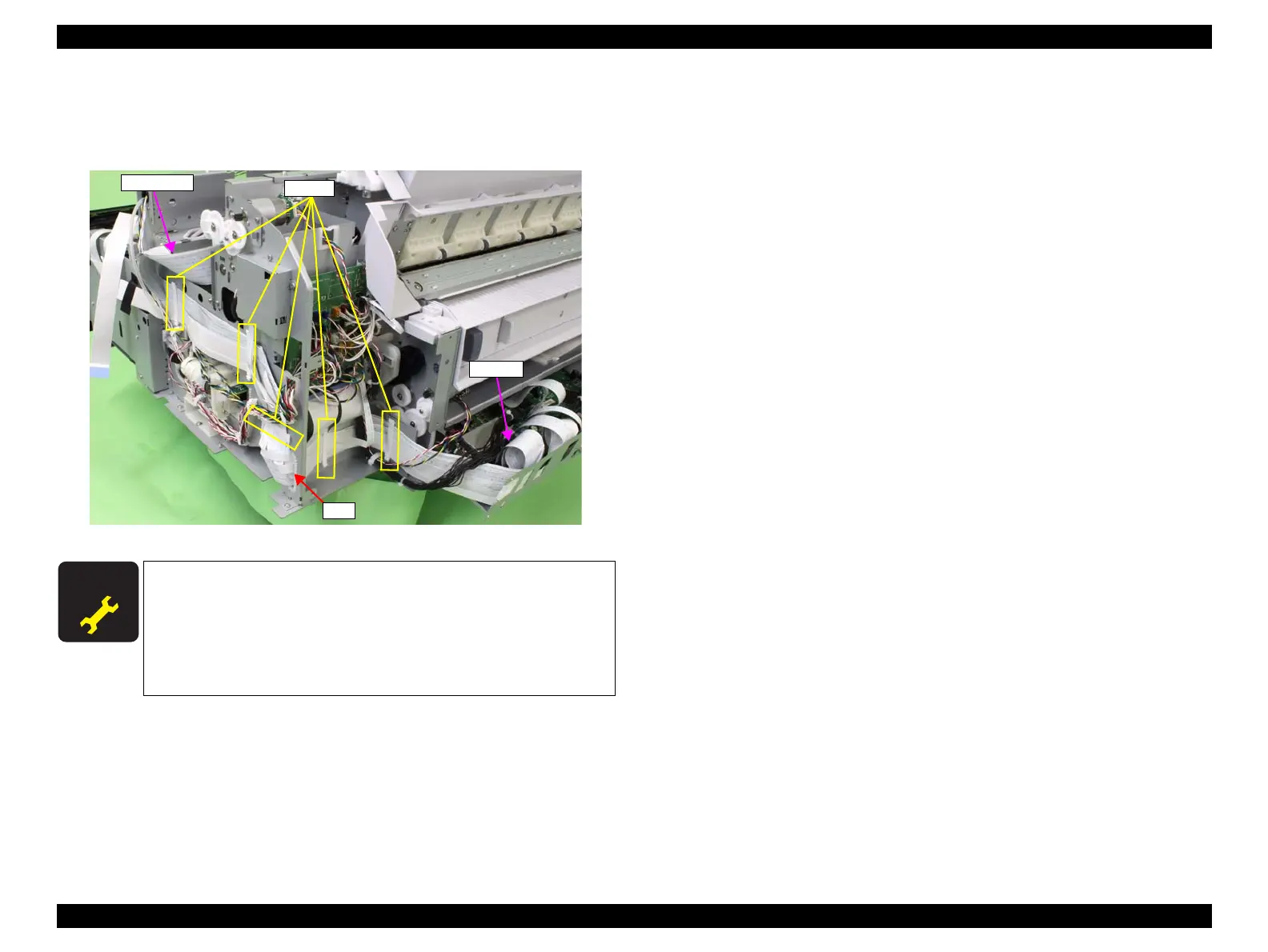
23. Release the Head FFC from the five clams, and pull it out from the hole of the
main frame.
24. Disconnect the Head FFC (CN100) from the Main Board.
Figure 3-187. Removing the Head FFC
A D J U S T M E N T
R E Q U I R E D
Be sure to refer to Chapter 4 “Adjustment” (see p277) and perform
specified adjustments after replacing or removing the Head FFC.
<Adjustment items>
1. FFC Position Check
2. Nozzle Check
3. CR & PF Direction Head Slant Adjustment
CN100
Hole
Head FFC
Clamps
 Loading...


