Epson Stylus Pro 4900/Epson Stylus Pro 4910 Revision A
DISASSEMBLY & ASSEMBLY Disassembly and Assembly Procedure 254
Confidential
3.4.9.14 Decompression Pump
1. Remove the Front Cover. (p142)
2. Remove the Control Panel Cover. (p136)
3. Remove the Right Upper Cover. (p138)
4. Remove the Right Cover. (p139)
5. Remove the Rear Cover. (p144)
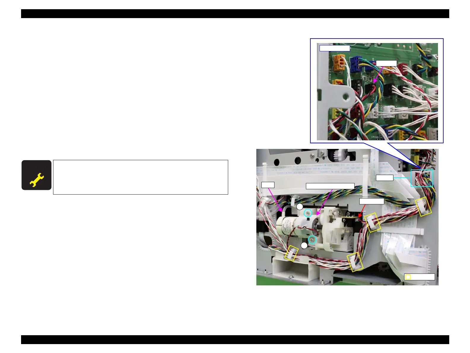
6. Disconnect the connector (CN232) from the SUB-C Board.
7. Release the harnesses from the four clamps and the saddle.
8. Pull out the tube from the Decompression Pump.
9. Remove the two screws that secure the Decompression Pump, and remove the
Decompression Pump.
A) Silver, Phillips, Bind machine screw M3x8: two pieces
Figure 3-192. Removing the Decompression Pump
A D J U S T M E N T
R E Q U I R E D
Be sure to refer to Chapter 4 “Adjustment” (see p277) and perform
specified adjustment after replacing the Decompression Pump.
<Adjustment item>
Counter Reset (Decompression Pump Counter)
A
SUB-C Board
CN232
A
Clamp
Decompression Pump
Connector
Saddle
Tube
 Loading...


