Epson Stylus Pro 4900/Epson Stylus Pro 4910 Revision A
DISASSEMBLY & ASSEMBLY Disassembly and Assembly Procedure 170
Confidential
3.4.4.2 CR Encoder
1. Remove the Front Cover. (p142)
2. Remove the Right Upper Cover. (p138)
3. Remove the Control Panel Cover. (p136)
4. Remove the Right Cover. (p139)
5. Remove the Left Cover. (p137)
6. Unlock the CR Unit, and move the CR Unit to the left side. (p124)
7. Remove the CR Scale. (p171)
8. Remove the APG Motor Assy. (p179)
9. Remove the CR Cover. (p149)
10. Remove the Ink Selector Assy from the CR Unit.
(Step 9 to Step 14 in “3.4.9.1 Ink Selector Assy” (P. 229))
11. Remove the Printhead. (p232)
12. Remove the CR Unit/CR Belt. (p175)
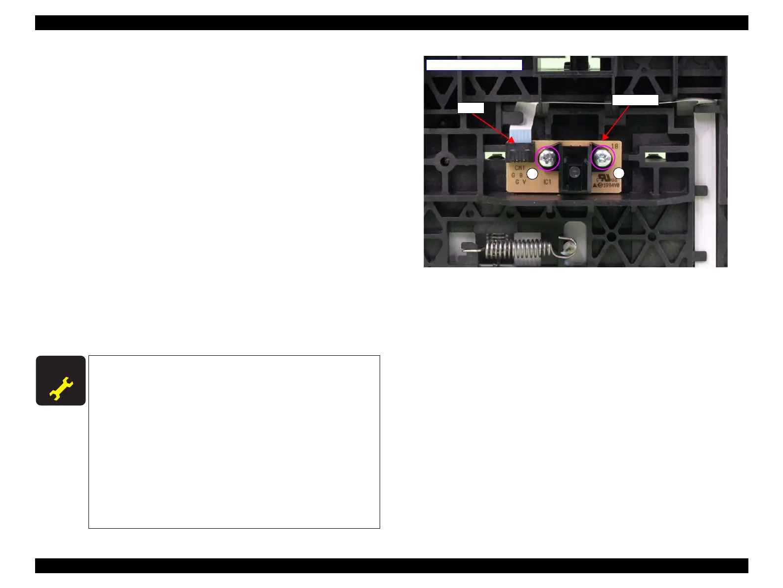
13. Remove the two screws that secure the CR Encoder, and remove the CR Encoder.
A) Silver, Phillips, Bind P-tite M2.5x6 (bit: No.1): two pieces
14. Disconnect the FFC from the CR Encoder.
Figure 3-80. Removing the CR Encoder
A D J U S T M E N T
R E Q U I R E D
Be sure to refer to Chapter 4 “Adjustment” (see p277) and perform
specified adjustments after replacing or removing the CR Encoder.
<Adjustment items>
1. FFC Position Check
2. CR Belt Adjustment
3. PG Height Check & Adjustment
4. Nozzle Check
5. CR & PF Direction Head Slant Adjustment
6. CR Encoder and Scale Check
7. Active Damper Adjustment
8. Ink Mark Sensor Check & Adjustment
9. PW + T&B&S Check & Adjustment
10. Auto Bi-D Adjustment
CR Encoder
A
- Rear of Carriage Unit -
A
FFC
 Loading...


