Epson Stylus Pro 4900/Epson Stylus Pro 4910 Revision A
DISASSEMBLY & ASSEMBLY Disassembly and Assembly Procedure 134
Confidential
3.4.2.2 Printer Cover Sensor
1. Remove the Front Cover. (p142)
2. Remove the Right Upper Cover. (p138)
3. Remove the Control Panel Cover. (p136)
4. Remove the Right Cover. (p139)
5. Remove the Left Cover. (p137)
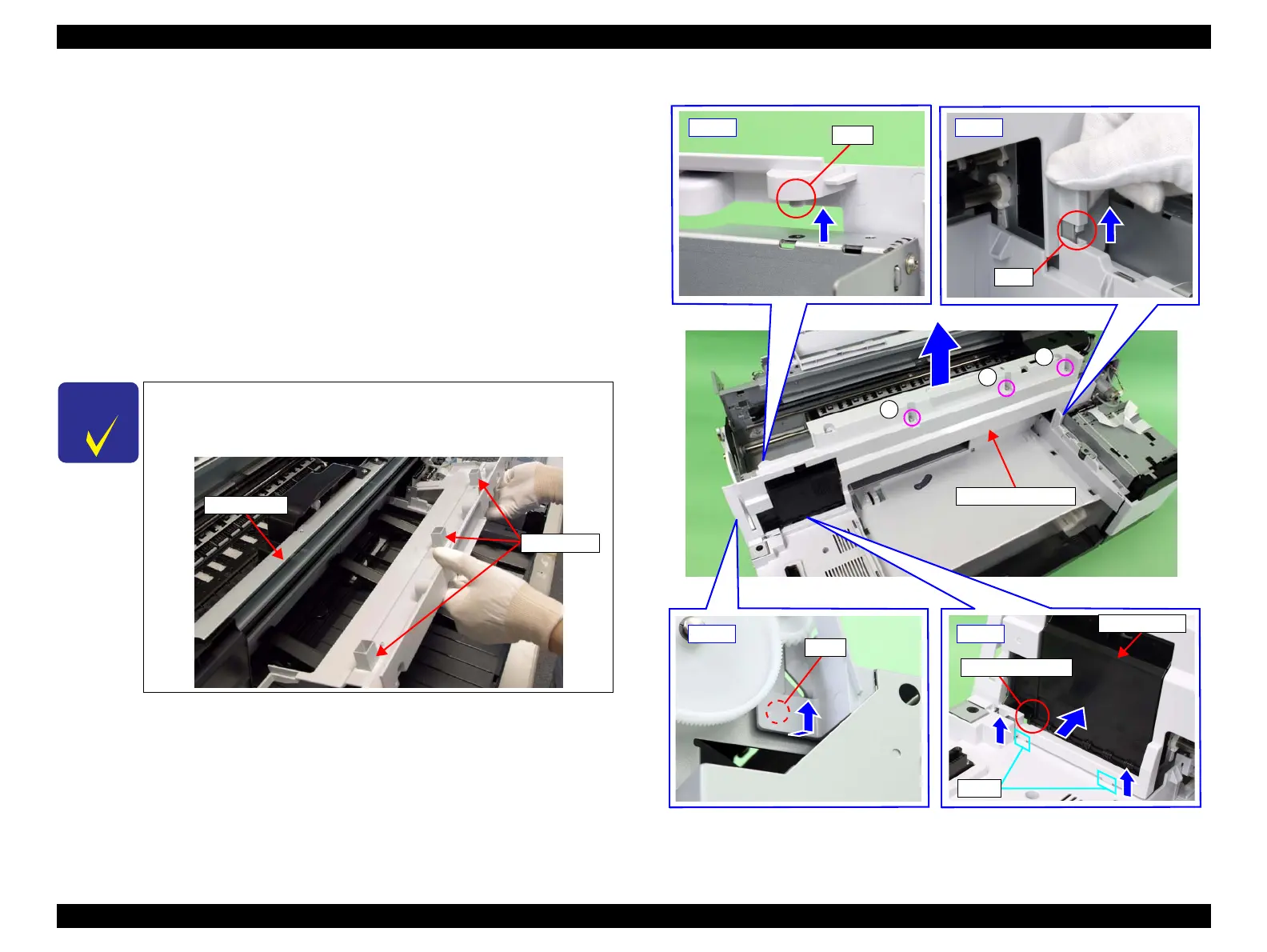
6. Remove the three screws that secure the upper front cover.
A) Silver, Phillips, Bind S-tite with S.W & P.W. M4x10: three pieces
7. Lift the lower right of the upper front cover to release the tab.
8. Lift the upper left of the upper front cover to release the dowel.
9. Pull the part of the upper front cover circled in the figure outward and lift it in the
direction of the arrow to release the dowel.
10. While pushing the Cutter Cover and releasing the contact with the upper front
cover, lift the upper front cover to release the ribs, and remove the upper front
cover.
Figure 3-30. Removing the upper front cover
C H E C K
P O I N T
When removing the upper front cover in the following steps, pull it
toward you taking care not to hit the protrusion on the bottom
against the main frame.
Main frame
protrusions
Upper front cover
A
Tab
Dowel
Dowel
Cutter Cover
Interference part
Ribs
A
A
Step7Step8
Step9 Step10
 Loading...


