Epson Stylus Pro 4900/Epson Stylus Pro 4910 Revision A
DISASSEMBLY & ASSEMBLY Disassembly and Assembly Procedure 264
Confidential
3.4.12 Color Measurement Device Parts
3.4.12.1 Main-C Board
1. Remove the Color Measurement Device. (p255)
2. Remove the Mounter. (p132)
3. Remove the Upper Cover. (p257)
4. Remove the I/F Cover. (p258)
5. Remove the Left Cover. (p260)
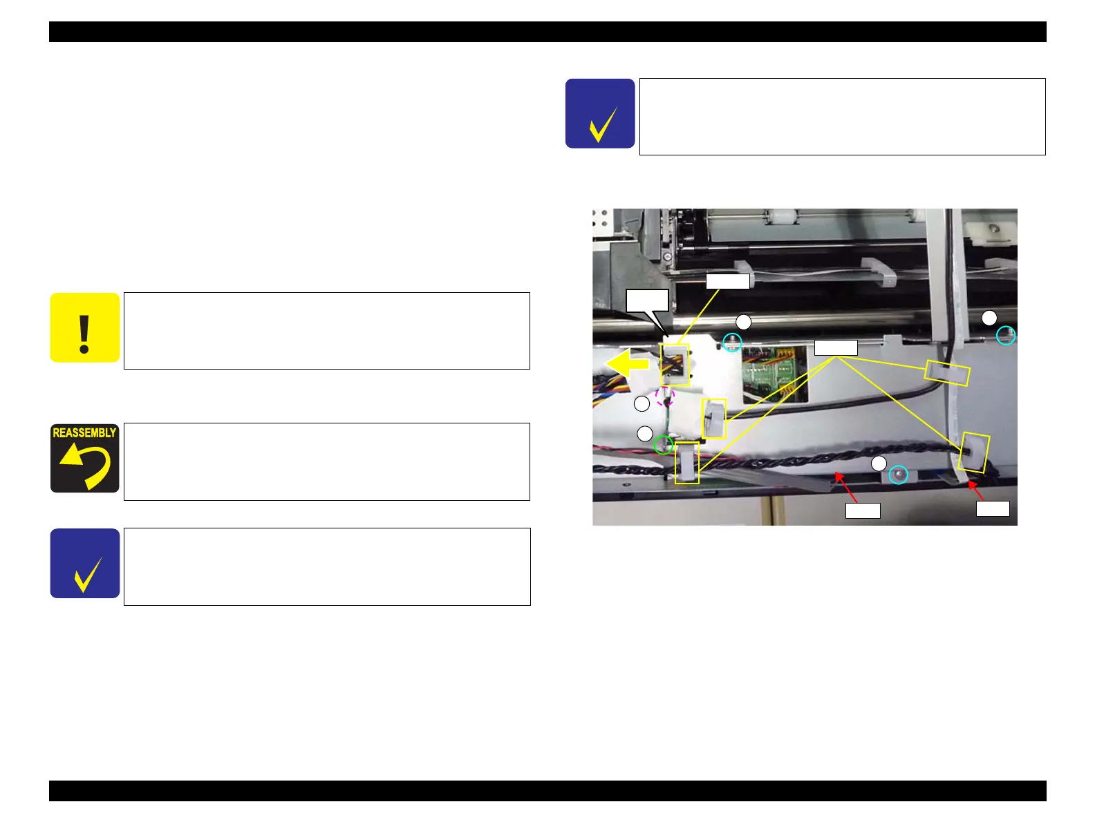
6. Release the harness from the clamps on the plate.
7. Remove the clamps shown in the figure from the plate.
8. Remove the five screws that secure the plate.
A) Silver, Phillips, Bind machine screw M3x6: three pieces
B) Silver, Phillips, Bind machine screw M3x8 (bit: No.1): one piece
C) Silver, Phillips, Bind machine screw M2.5x4 (bit: No.1): one piece
9. Remove the plate.
Figure 3-206. Removing the plate
C A U T I O N
When removing the clamps from the plate in the next step, make
sure not to break them.
Make sure to route the harness correctly as shown in Figure 3-206.
C H E C K
P O I N T
In the next step, make sure to confirm which screw is attached to
which location because various screws are used here.
C H E C K
P O I N T
If the FFC prevents removing the plate, disconnect the FFC from
the Main-C Board.
A
B
C
Plate
FFC
Step 7
A
A
Clamp
Clamp
 Loading...


