Epson Stylus Pro 4900/Epson Stylus Pro 4910 Revision A
DISASSEMBLY & ASSEMBLY Disassembly and Assembly Procedure 226
Confidential
3.4.8.3 Cutter HP Sensor
1. Remove the Front Cover. (p142)
2. Remove the Control Panel Cover. (p136)
3. Remove the Right Upper Cover. (p138)
4. Remove the Right Cover. (p139)
5. Remove the Left Cover. (p137)
6. Remove the Media Eject Cover. (p148)
7. Disconnect the connector (CN315) from the SUB-C board.
8. Release the harnesses from the four clamps and the saddle.
9. Pull out the harnesses from the hole of the main body frame.
Figure 3-157. Releasing the harnesses
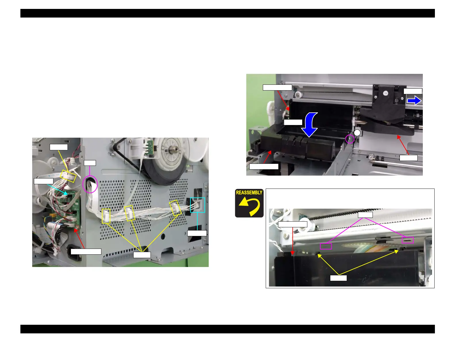
10. Move the cutter to the center.
11. Open the Cutter Cover.
12. Remove the screw that secures the cover holder, and remove the cover holder.
A) Silver, Phillips, Bind P-tite M3x8: one piece
Figure 3-158. Removing the cover holder
CN315
Clamps
Saddle
Hole
SUB-C Board
Clamp
When installing the cover holder, be sure to set the two hooks to the
holes of the main frame.
A
Cutter
Cover holder
Step 10
Step 11
Cutter Cover
Cover holder
Hooks
Holes
 Loading...


