Epson Stylus Pro 4900/Epson Stylus Pro 4910 Revision A
DISASSEMBLY & ASSEMBLY Disassembly and Assembly Procedure 157
Confidential
3.4.3.3 Power Supply Box
1. Remove the Front Cover. (p142)
2. Remove the Rear Cover. (p144)
3. Remove the Left Cover. (p137)
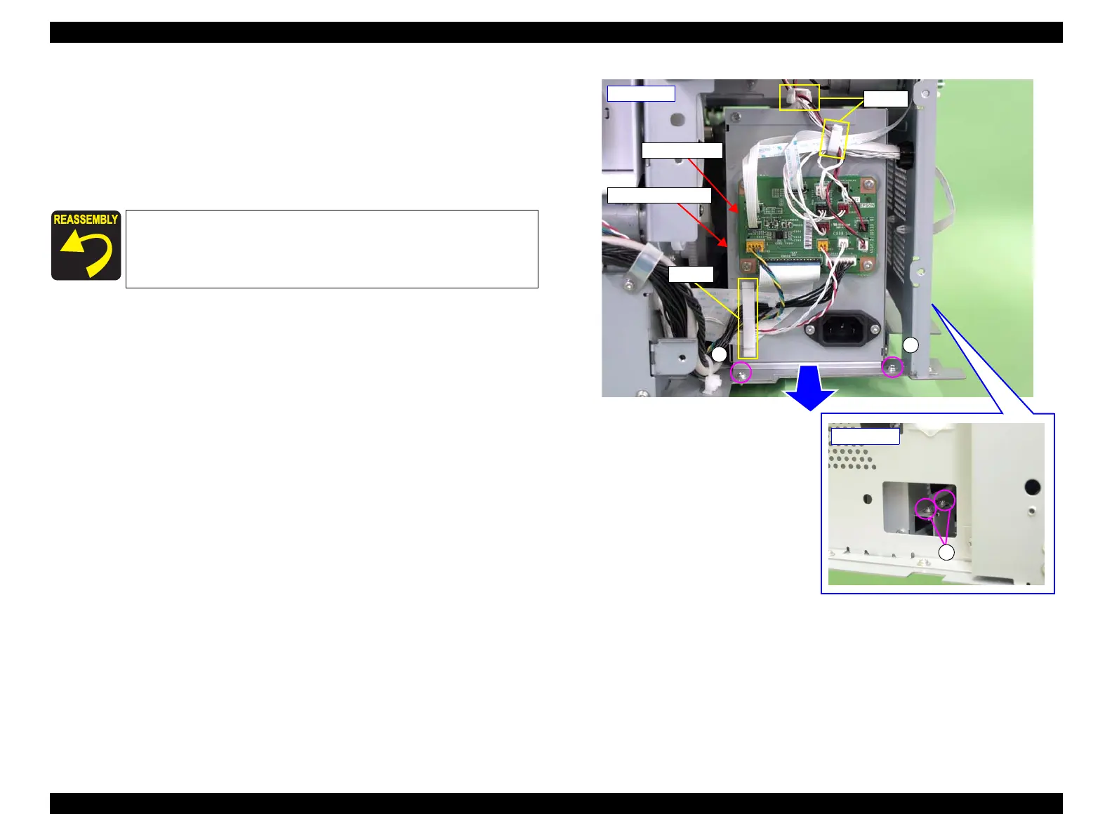
4. Disconnect all the connectors and FFCs on the SUB-C Board.
5. Release the harnesses from the three clamps.
6. Remove the four screws that secure the Power Supply Box.
A) Silver, Phillips, Round Washer Head S-tite M3x6: four pieces
7. Pull out the Power Supply Box.
Figure 3-61. Pulling out the Power Supply Box
When installing the SUB-C Board, be sure to refer to Chapter 6
“Appendix” (see p432) and connect the connectors correctly.
Power Supply Box
- Rear left -
A
SUB-C Board
A
Clamps
Clamp
A
- Left side -
 Loading...


