Epson Stylus Pro 4900/Epson Stylus Pro 4910 Revision A
DISASSEMBLY & ASSEMBLY Disassembly and Assembly Procedure 233
Confidential
3.4.9.3 IS Unit
1. Remove the Front Cover. (p142)
2. Remove the Control Panel Cover. (p136)
3. Remove the Right Upper Cover. (p138)
4. Remove the Right Cover. (p139)
5. Unlock the carriage, and move the CR Unit to the left end. (p124)
6. Remove the three screws that secure the AID Board Cover, and remove the AID
Board Cover.
A) Silver, Phillips, Bind machine screw M3x6: three pieces
Figure 3-166. Removing the AID Board Cover
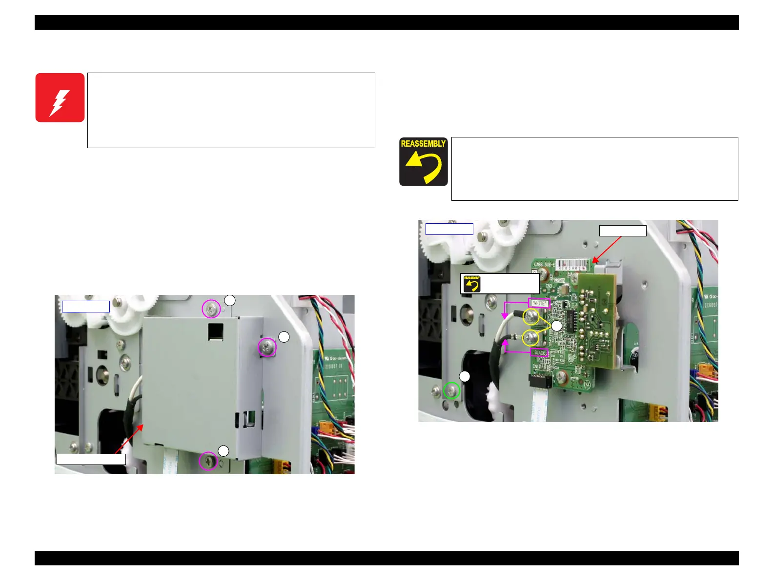
7. Remove the two screws that secure the terminal of the grounding wire, and remove
the terminal of the grounding wire.
B) Silver, Phillips, Bind S-tite with S.W & P.W. M3x6: two pieces
8. Remove the screw.
C) Silver, Phillips, Bind machine screw M3x6: one piece
Figure 3-167. Removing the terminal of the grounding wire
W A R N I N G
When powering this product, high-voltage current may be applied
on the IS Unit (Flushing Box). To prevent ELECTRIC SHOCK, do
not touch the IS Unit (Flushing Box) when the power is ON.
If the shock should happen, the flowing current is very tiny, about a
few hundreds μA, therefore it will not do any harm on the human
body.
AID Board Cover
- Left side -
A
A
A
Secure the terminal of the AID Board and the AID Board with
the same screw B. At this point, make sure to match the color
(WHITE/BLACK) of the cable with the color written on the
board.
Make sure to secure the screw B tightly.
- Left side -
Screw together
B
AID Board
C
 Loading...


