Epson Stylus Pro 4900/Epson Stylus Pro 4910 Revision A
DISASSEMBLY & ASSEMBLY Disassembly and Assembly Procedure 224
Confidential
3.4.8.2 Cutter Motor Assy
1. Remove the Front Cover. (p142)
2. Remove the Right Upper Cover. (p138)
3. Remove the Control Panel Cover. (p136)
4. Remove the Right Cover. (p139)
5. Remove the Left Cover. (p137)
6. Remove the Media Eject Cover. (p148)
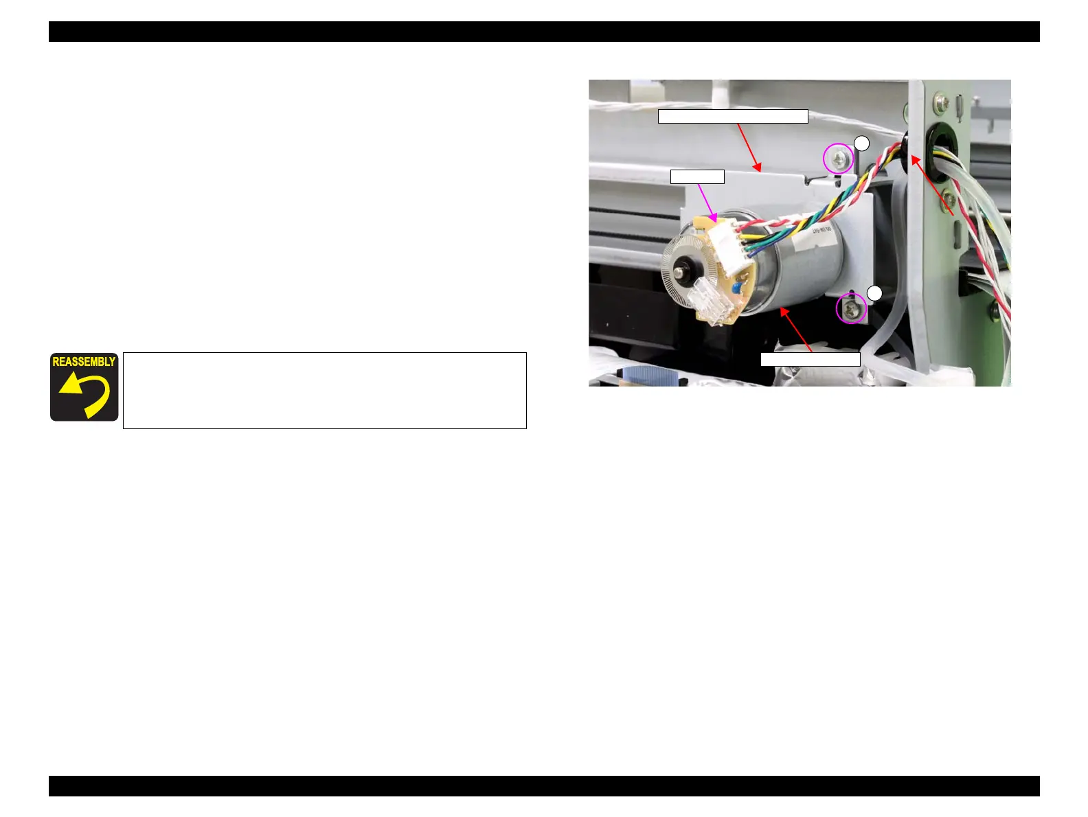
7. Disconnect the connector from the Cutter Motor Assy.
8. Remove the two screws that secure the cutter motor mounting plate.
A) Silver, Phillips, Bind machine screw M3x6: two pieces
9. Remove the cutter motor mounting plate from the main body.
Figure 3-155. Removing the cutter motor mounting plate
When installing the cutter motor mounting plate, be careful of the
installation directions of the gear and the pulley referring to Figure
3-156.
A
Connector
Cutter motor mounting plate
A
Cutter Motor Assy
 Loading...


