Epson Stylus Pro 4900/Epson Stylus Pro 4910 Revision A
DISASSEMBLY & ASSEMBLY Disassembly and Assembly Procedure 274
Confidential
11. Release the harness, and disconnect the connector from the Backing Sensor.
12. Disengage the hook that secures the Backing Sensor, and remove the Backing
Sensor from the tile guide.
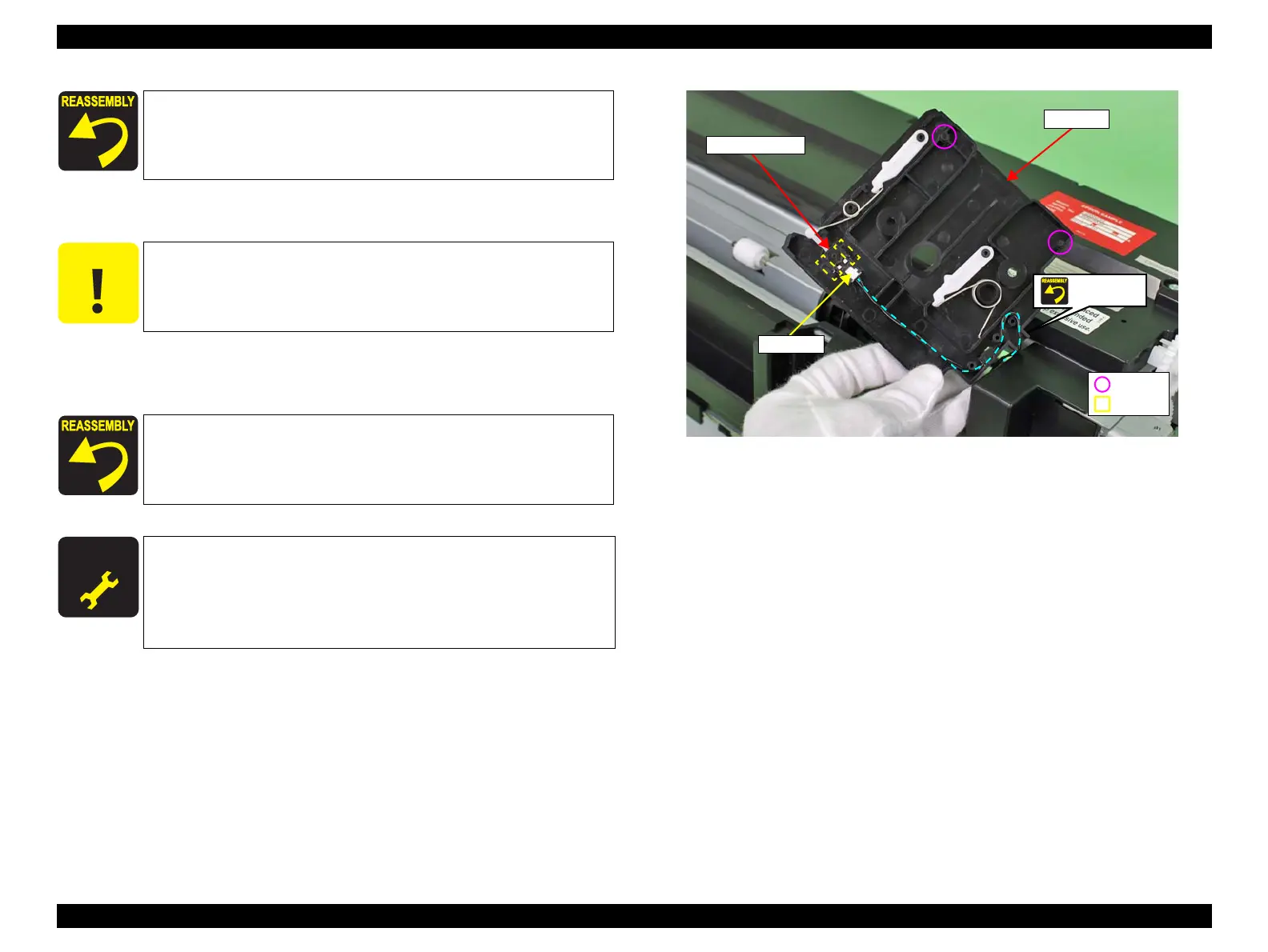
Figure 3-218. Removing the Backing Sensor
When installing the tile guide, align the dowels of the tile guide with
the positioning holes of the main unit.
C A U T I O N
When removing the Backing Sensor from the tile guide in the next
step, be careful not to let any of the parts attached to the tile guide
come off. If any of them comes off, reattach it referring to Figure
3-218.
When installing the Backing Sensor, not to catch the harness of the
Backing Sensor, route the harness correctly as shown in Figure
3-218.
A D J U S T M E N T
R E Q U I R E D
Be sure to refer to Chapter 4 “Adjustment” (see p277) and perform
specified adjustment after replacing or removing the Backing
Sensor.
<Adjustment item>
Spectroproofer Sensor Check
Backing Sensor
Connector
Tile guide
Hook
Dowel
Routing
 Loading...


