Epson Stylus Pro 4900/Epson Stylus Pro 4910 Revision A
DISASSEMBLY & ASSEMBLY Disassembly and Assembly Procedure 275
Confidential
3.4.12.8 CR Motor
1. Remove the Color Measurement Device. (p255)
2. Remove the Mounter. (p132)
3. Remove the Upper Cover. (p257)
4. Remove the I/F Cover. (p258)
5. Remove the Right Cover. (p259)
6. Remove the Left Cover. (p260)
7. Open the Front Cover, and move the carriage to the right.
(Step 6 in “3.4.12.5 Paper Pressing Motor” (P. 269))
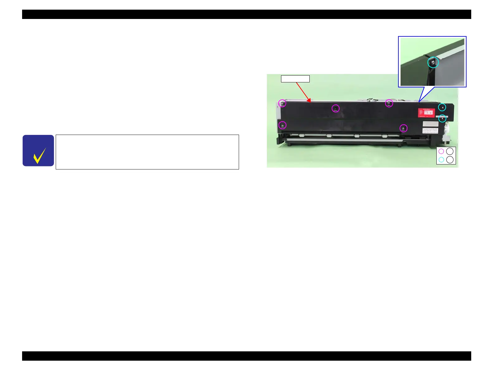
8. Remove the eight screws that secure the Rear Cover.
A) Silver, Phillips, Round Washer Head S-tite M3x8: five pieces
B) Silver, Phillips, Bind P-tite M3x8: three pieces
9. Remove the Rear Cover.
Figure 3-219. Removing the Rear Cover
C H E C K
P O I N T
In the next step, make sure to confirm which screw is attached to
which location because various screws are used here.
A
B
Rear Cover
 Loading...


