Epson Stylus Pro 4900/Epson Stylus Pro 4910 Revision A
DISASSEMBLY & ASSEMBLY Disassembly and Assembly Procedure 197
Confidential
3.4.5.10 Release Motor Assy
1. Remove the Front Cover. (p142)
2. Remove the Left Cover. (p137)
3. Remove the Rear Cover. (p144)
4. Disconnect the two connectors (CN305, CN307) from the SUB-C Board.
5. Release the harnesses from the two clamps.
6. Disconnect the FFC from the encoder.
7. Remove the two screws that secure the motor mounting plate, and remove the
motor mounting plate.
A) Silver, Phillips, Bind machine screw M3x6: two pieces
Figure 3-116. Disconnecting the connectors
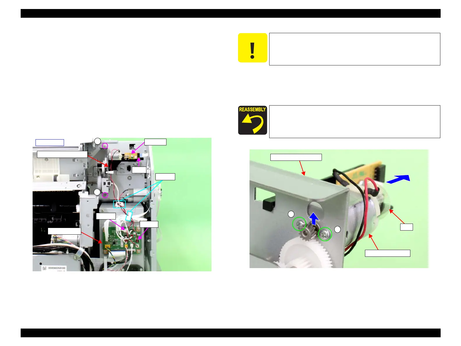
8. Remove the two screws that secure the Release Motor Assy, and remove the
Release Motor Assy.
B) Silver, Phillips, Pan machine screw M2.6x3: two pieces
Figure 3-117. Removing the Release Motor Assy
Motor mounting plate
- Rear left -
A
A
CN305
CN307
Clamps
FFC
Encoder
SUB-C Board
C A U T I O N
When removing the Release Motor Assy in the next step, be careful
not to damage the scale.
When installing the Release Motor Assy, be careful of the
installation direction referring to Figure 3-117.
Motor mounting plate
B
B
Release Motor Assy
Scale
 Loading...


