Epson Stylus Pro 4900/Epson Stylus Pro 4910 Revision A
DISASSEMBLY & ASSEMBLY Disassembly and Assembly Procedure 198
Confidential
3.4.5.11 Release Sensor
1. Remove the Front Cover. (p142)
2. Remove the Left Cover. (p137)
3. Remove the Rear Cover. (p144)
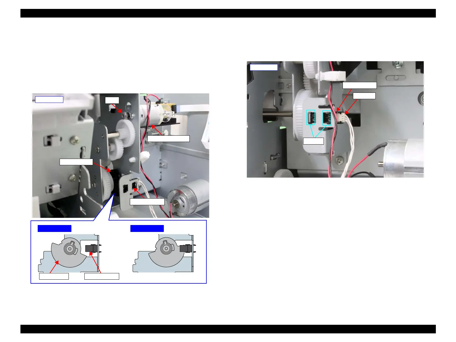
4. Rotate the gear of the Release Motor Assy until the cutout of the shading plate
comes between the Release Sensor’s detector section.
Figure 3-118. Rotating the Shading Plate
5. Disengage the hooks that secure the Release Sensor, and remove the Release
Sensor.
6. Disconnect the connector from the Release Sensor.
Figure 3-119. Removing the Release Sensor
- Left rear -
Gear
Shading plate
Release Motor Assy
Release Sensor
Removable
Shading plate
Release Sensor
Unremovable
Release Sensor
- Left rear -
Connector
Hooks
 Loading...


