Epson Stylus Pro 4900/Epson Stylus Pro 4910 Revision A
DISASSEMBLY & ASSEMBLY Disassembly and Assembly Procedure 228
Confidential
3.4.8.4 Cutter Unit
1. Remove the Front Cover. (p142)
2. Remove the Control Panel Cover. (p136)
3. Remove the Right Upper Cover. (p138)
4. Remove the Right Cover. (p139)
5. Remove the Left Cover. (p137)
6. Remove the Media Eject Cover. (p148)
7. Remove the Cutter Cover. (p223)
8. Remove the Cutter. (p127)
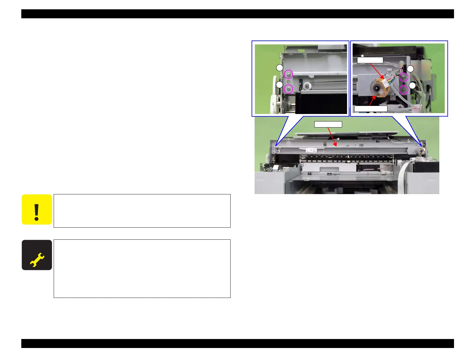
9. Disconnect the connector of the Cutter HP Sensor, and release the harness. (Step 7
to Step 9 in “3.4.8.3 Cutter HP Sensor” (P. 226))
10. Disconnect the connector from the cutter motor.
11. Remove the four screws that secure the Cutter Unit.
A) Silver, Phillips, Bind machine screw M3x6: four pieces
12. While pulling out the harness of the Cutter HP Sensor, remove the Cutter Unit.
Figure 3-160. Removing the Cutter Unit
C A U T I O N
When replacing the Cutter Unit, check the cutter belt tension
before attaching the Cutter Unit. (see p381)
A D J U S T M E N T
R E Q U I R E D
Be sure to refer to Chapter 4 “Adjustment” (see p277) and perform
specified adjustments after replacing or removing the Cutter Unit.
<Adjustment items>
1. Counter Reset (Cutter Motor Assy Counter)
2. Cutter Belt Tension Check
3. Sensor Check (Cutter HP Sensor)
4. Cut Position Check & Adjustment
A
Connector
A
A
A
Cutter Unit
Cutter motor
 Loading...


