159
────────────────────────────────────────────────────
8.7 FFT Analysis Function
────────────────────────────────────────────────────
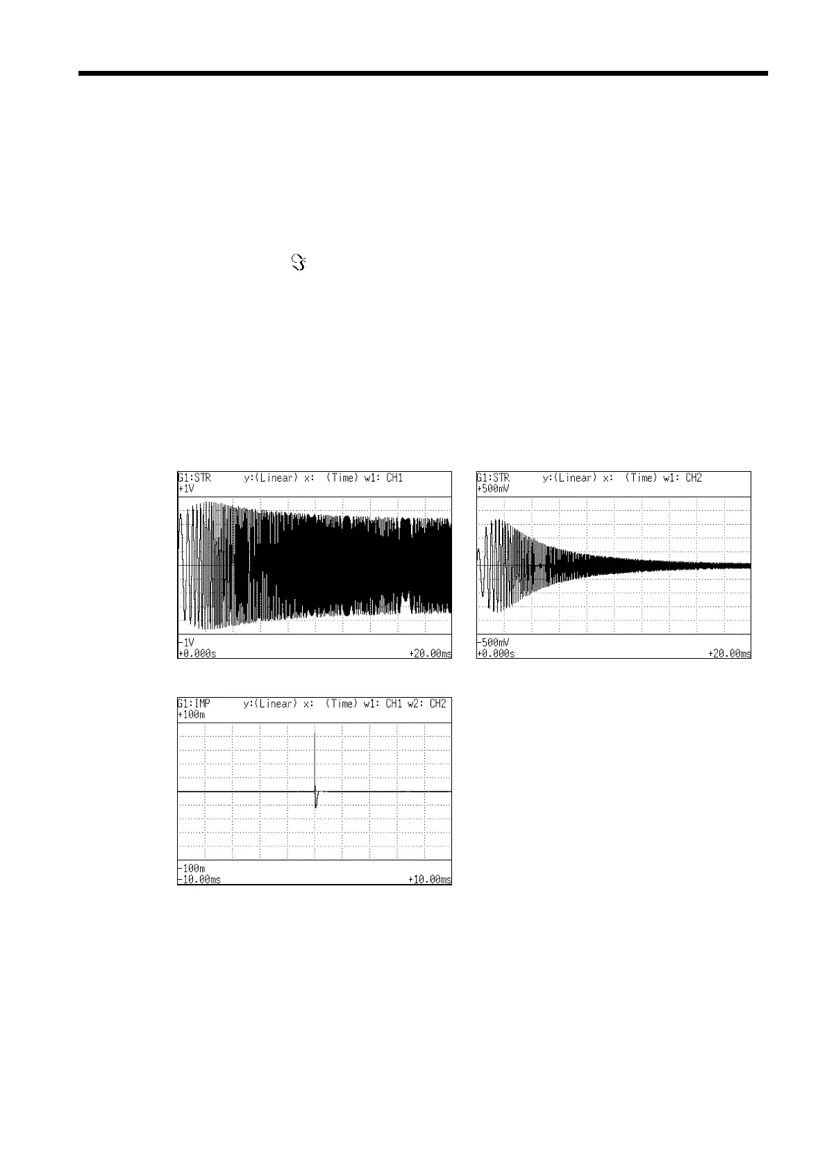
8.7.10 Unit Impulse Response [IMP]
Function
Horizontal
cursor
Vertical
cursor
Stored waveform (input signal) Stored waveform (output signal)
Unit impulse response
40, 41, 57
Displays the frequency response of a system in the time domain.
A response waveform equivalent to the unit impulse function is obtained by
analyzing the input and output signals of the system being measured.
Major applications
Checking circuit time constants.
IMP =
-1
(Hab)
Time Time display. The center indicates the reference (τ=0), the
right side indicates time lag (+τ), and the left side indicates
time lead (-τ).
Linear Inverse Fourier conversion value of the transfer function (Hab)
(no units).
Example Unit impulse response waveforms