89
────────────────────────────────────────────────────
6.3 ST ATUS Settings (RMS)
────────────────────────────────────────────────────
1
2
3
4
5
6
7
8
9
10
11
12
13
14
A
NOTE
6.3.5 Setting the Display Layout
Flashing cursor
Function
display
Meaning
##F2
:
Move the cursor up in the selection window.
:
Move the cursor down in the selection window.
Graph
Analog
channel
Graph
Analog
channel
1
CH 1
9
CH19
2
CH 2
10
CH 10
3
CH 3
11
CH 11
4
CH14
12
CH 12
5
CH15
13
CH 13
6
CH16
14
CH 14
7
CH17
15
CH 15
8
CH18
16
CH 16
・
The maximum recording length is 2000 divisions for a memory capacity of
8 M words or 10,000 divisions for 32 M words (with additional memory).
・
When the recording length is set to
CONT.
, the auto-saving is automatically
set to OFF.
・
In fixed-length recording mode, the symbol "*" in the selection window
indicates the recording length of the data stored to current memory. (If no
data is present in memory, this symbol is not displayed.) In any recording-
length mode, the symbol "#" is displayed before the recording length.
・
The layout can be set for showing input signals on the screen display and
recording them on the printer.
・
The following layout is available: single, dual, quad, oct (Waveform display
screen), and hex (Print only, Display oct
)
.
・
The voltage per division is automatically changed according to the display
format.
Procedure
Screen: STATUS
1. Press the STATUS key to display the STATUS screen.
2. Move the flashing cursor to the format item.
3. Use the function keys to select the display format.
4. Set the graph type when the display format is set to DUAL, QUAD, OCT or
HEX screen display.
5. Press the CHAN key to display the CHANNEL screen.
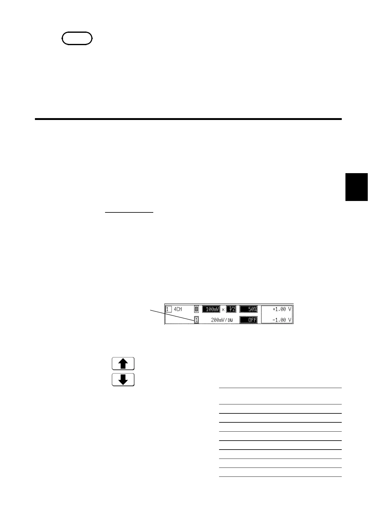
6. Move the flashing cursor to the point in the figure below.
The figure shows the setting for the channel 1 (CH1). Setting for the channel
2 to 16 should be made in the same way.
7. Use the function keys to select.
In the cases of HEX, as far as the
printer recording output is
concerned, the waveforms for each
channel are automatically distributed
on each graph according to the table
below:
For details on logic channels, refer
to Section 9.3.8.