266
────────────────────────────────────────────────────
12.3 SCALING Screen (SYSTEM 2)
────────────────────────────────────────────────────
12.2.16 Variable Auto Calibration
Function
display
Meaning
:
The variable settings are not changed even if
the scaling or voltage axis range settings are
altered.
:
The variable settings are changed in
conjunction with changes to the scaling or
volta
eaxisran
esettin
s.
s103
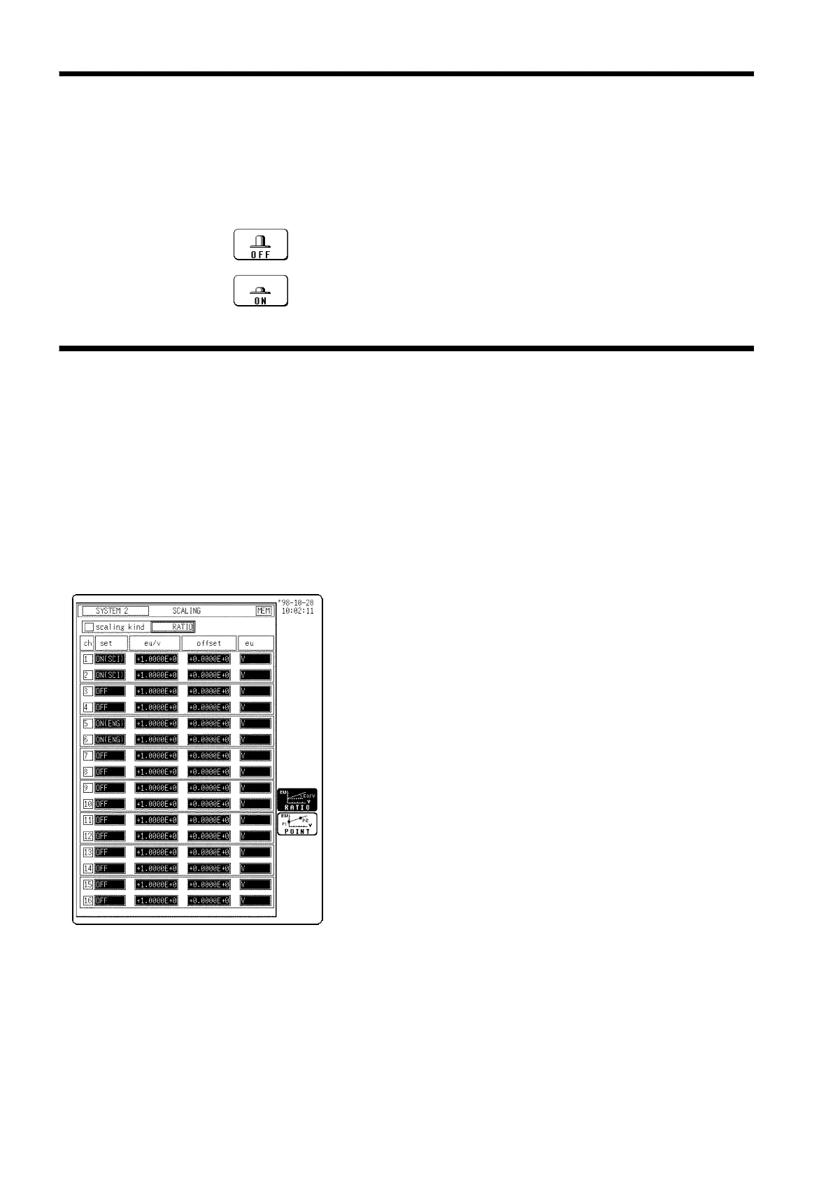
12.3 SCALING Screen (SYSTEM 2)
This automatically calibrates the variable settings in conjunction with
changes to the scaling and voltage axis range settings.
・The scaling function can be used to convert an output voltage from a sensor
or similar into a physical quantity.
・Two types of scaling functions are available.
・The gauge scale (maximum and minimum values of vertical axis) and A・B
cursor measurement values are displayed in the scaled units.
・Scaling can be performed for every channel.
(1) Conversion ratio method
Scaling is performed by specifying a physical quantity
to correspond to a 1 V input signal (conversion ratio:
eu/v), an offset value, and the unit (eu: engineering
units). This will cause the measurement voltage to be
converted into the selected units.
(2) 2-point method
Scaling is performed by specifying two input signal
points (voltage values) and the conversion values for
these two points in engineering units (eu). This will
cause the measurement voltage to be converted into the
selected units.
For details, see Section 9.8.