238
────────────────────────────────────────────────────
10.9 Logic Trigger
────────────────────────────────────────────────────
1. 2. 3.
Function
display
Meaning
:
Logic trigger is not used.
:
Triggering occurs if any one of the logic input
signals conforms to the trigger pattern.
:
Triggering only occurs if all of the logic input
signals conforms to the trigger pattern.
Function
display
Meaning
:
Trigger filter is disabled.
:
Trigger filter is enabled.
Filterwidthis10ms.
10.9 Logic Trigger
・
The signal of a logic channel can be used as trigger source.
・
A trigger pattern and logical operator (AND/OR) are specified, and
triggering occurs when the trigger conditions are met.
・
A trigger filter can be specified, so that triggering occurs only when the
trigger conditions are met within the filter width.
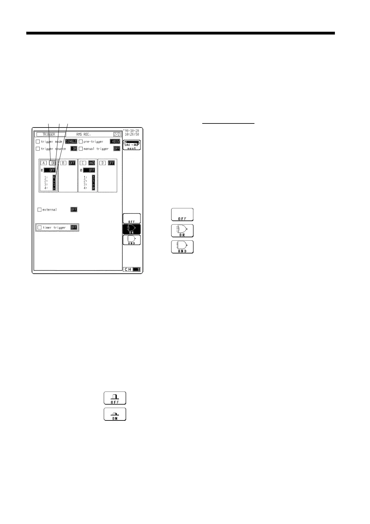
Procedure
Screen: TRIGGER
s89
(1) Set the logic trigger AND/OR linking
1. Use the TRIG key and the CH.SET key to display the
screen shown in the figure.
2. Move the flashing cursor to position
1. shown in the
figure.
3. Use the function keys to select the setting.
(2) Set the trigger filter
1. Move the flashing cursor to position
2.
shown in the figure.
2. Use the Jog/Shuttle control or the function keys to make the selection.
In the Memory recorder, Recorder&Memory, FFT Functions
OFF
Trigger filter is disabled
0.1
to
10.0
Trigger filter is enabled. Filter width is specified using
divisions
In the Recorder and RMS recorder functions