42
────────────────────────────────────────────────────
4.3 ST ATUS Settings (MEM)
────────────────────────────────────────────────────
4.3.1 Setting the Function Mode
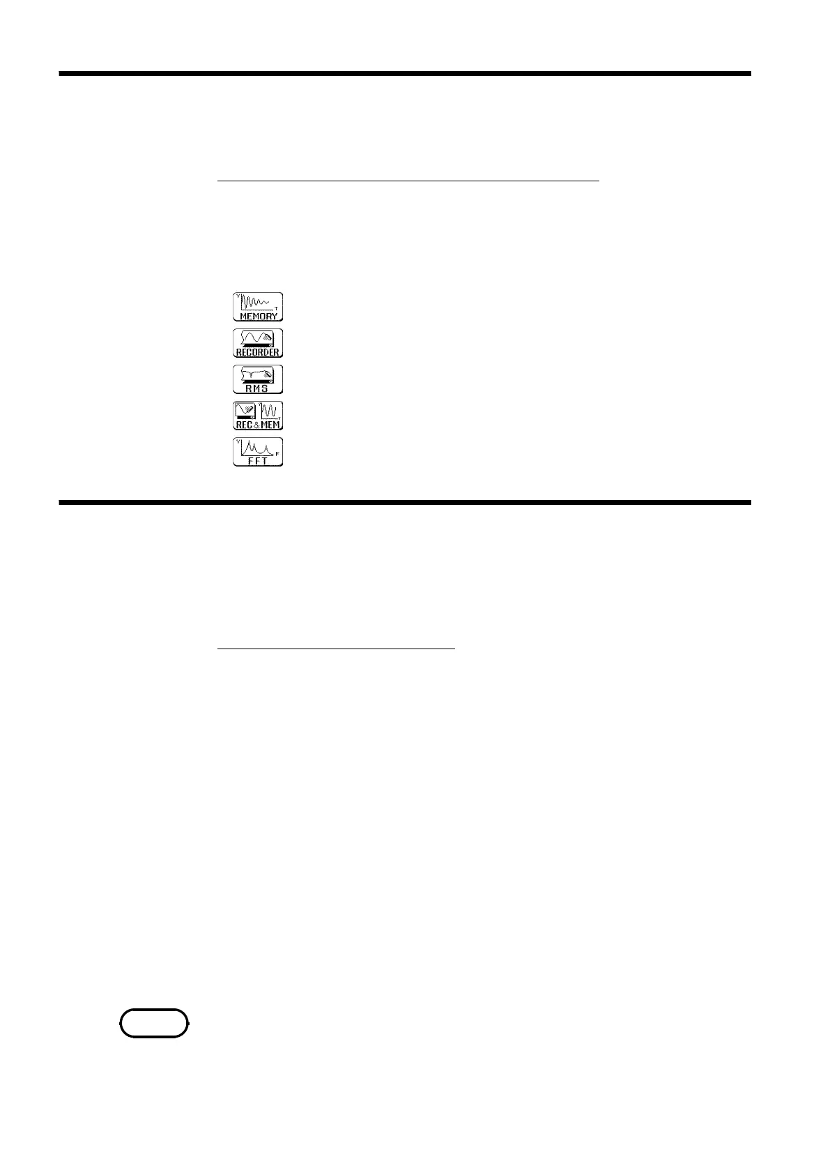
Function
display
Meaning
:
Memory recorder function
:
Recorder function
:
RMS recorder function
:
Recorder & Memory recorder function
:
FFT function
4.3.2 Setting the Time Axis Range
NOTE
The 8841/42 has five function modes. Select the Memory recorder function.
Procedure
Screen: STATUS1, CHANNEL, TRIGGER, Waveform display
1. Use the Menu keys to display the desired screen.
2. Move the flashing cursor to the top position.
3. Select the
MEMORY
function key display.
Set the speed for inputting and storing the waveform of the input signal.
Time axis range setting expresses the time for 1 division. The sampling
period is 1/100th of the set value for the time axis range. (100 samples/DIV)
Screen: STATUS1, Waveform display
Procedure1
1. Use the Menu keys to display the desired screen.
2. Move the flashing cursor to the
time/DIV
item.
3. Use the Jog/Shuttle control, the function keys or the
TIME/DIV
key to make
the selection. When "EXT." is selected, the external sampling can be used.
For details, see Section 17.1.4.
Data points per division are set when external sampling is selected.
1. Move the flashing cursor to the
samples/DIV
item, as shown in the figure on
the left.
2. Use the
JOG/SHUTTLE
control or the function keys to make the selection.
Setting range is 10 to 1000.
Procedure 2
Using the TIME/DIV key
1. Use the Menu keys to display the desired screen.
2. Use the
TIME/DIV
key to make the selection.
The
TIME/DIV
key can be used regardless of where the flashing cursor is
located.
The symbol "*" in the selection window indicates the time axis of the data
stored to current memory. (If no data is present in memory, this symbol is
not displayed.)