381
────────────────────────────────────────────────────
17.1 External Input/Output Terminals
────────────────────────────────────────────────────
16
17
18
19
5
6
7
8
9
10
11
12
13
14
A
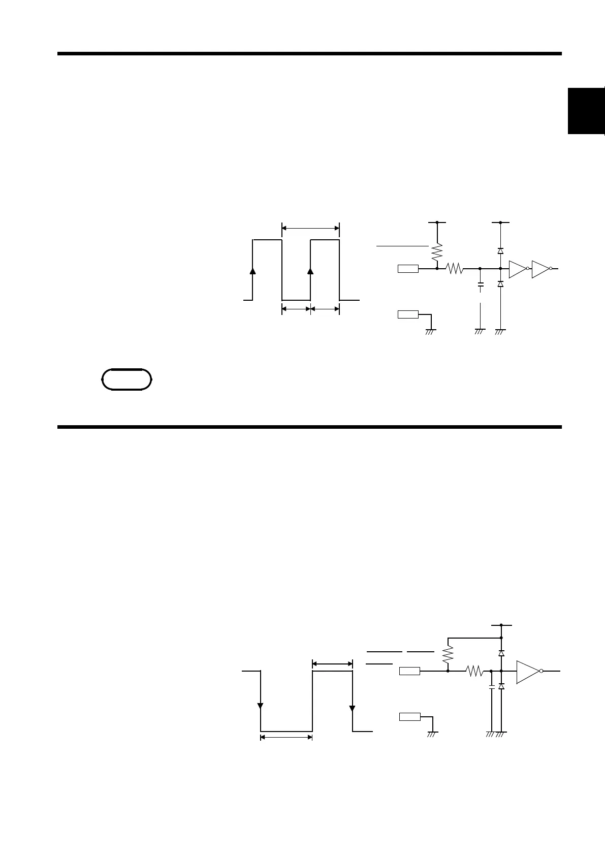
17.1.4 External Sampling Terminal [EXT SMPL]
HIGH
2.5 to 5.0V
LOW
0to1.0V
t
H
>
min. 0.5
μ
s
t
L
>
min. 0.5
μ
s
t
>
min. 2
μ
s
10 k
Ω
5V
1k
Ω
GND
EXT SMPL
t
t
t
150
F
NOTE
17.1.5 External Print Terminal / External Start/Stop Terminal
HIGH
2.5 to 5.0V
LOW
0to1.0V
40 ms min.
25 ms min.
3.3 k
Ω
5V
GND
START/STOP/
PRINT
470
Ω
2200
F
An external signal can be used to set the sampling rate.
Signal input method
・Input a pulse signal (High level: 2.5 to 5.0 V, Low level: 0 to 1.0 V) or a
square wave signal to the terminal to ground.
・Triggering is activated at the falling edge of the input waveform.
Voltage range High level: 2.5 to 5.0 V, Low level: 0 to 1.0 V
Pulse width High/Low level: 0.5μsmin.
Maximum input voltage -5 to 10 V
The external sampling can be used in Memory recorder function and FFT
function. To use external sampling, set the time-axis range (memory
recorder) and frequency range (FFT) to "EXT."
PRINT terminal Printing starts when a signal is input here.
START terminal Measurement starts when a signal is input here.
STOP terminal Measurement and printing stop when a signal is input here.
Signal input method
・Short the terminal to ground, or input a pulse signal (High level: 2.5 to 5.0
V, Low level: 0 to 1.0 V) or a square wave signal.
・Control is activated at the falling level of the input waveform (active Low).
Voltage range High level: 2.5 to 5.0 V, Low level: 0 to 1.0 V
Pulse width High level: 25 ms min. , Low level: 40 ms min.
Maximum input voltage -5 to 10 V