172
────────────────────────────────────────────────────
9.3 Setting the CHA NNEL Screen
────────────────────────────────────────────────────
9.3.6 Setting the Zero Position
Function
display
Meaning
:
Changes the +10% zero position
:
Changes the +1% zero position.
:
Changes the -1% zero position.
:
Changes the -10% zero position.
NOTE
100%
50%
0%
1600
LSB
0V0
2047
-2047
4095
/D data
/D data
RMS recorder function
Memory recorder function
Recorder function
Displayed screen
(zero position: 100%)
Displayed screen
(zero position: 0%)
Displayed screen
(zero position: 50%)
Magnification ratio:
×
1
The position of the zero voltage is set.
Procedure
Screen: CHANNEL,Waveform display
1. Use the Menu keys to display the desired screen.
2. Press the CH.SET key to display channel to be set.
3. Move the flashing cursor to the 0 pos. item.
4. Use the function keys, the Jog/Shuttle control, or
POSITION
knob to make a
setting.
・ The POSITION knob can be used regardless of where the flashing cursor is
located, if the CHANNEL or Waveform display screen is displayed.
・ Magnification/compression along the measurement range is performed using
the center of the screen as reference,even if the magnification/compression
ratio is changed.
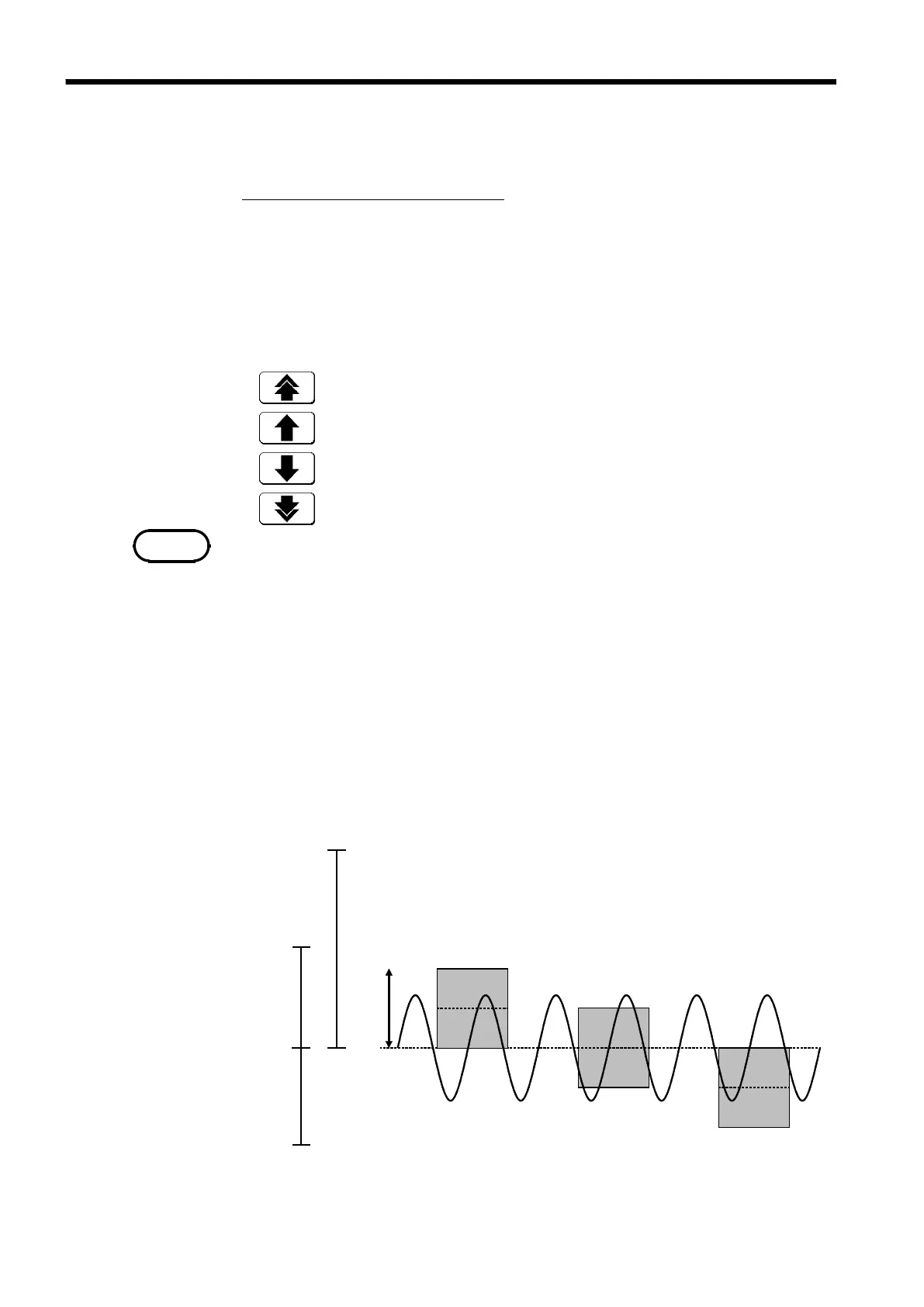
・ The zero positions are shown in the figure below. It is possible to display
the hidden portion of the waveform by setting "0 V" to a proper percentage
on the display.
・ Values that can be measured in each range are about 1.25 times the full-
scale voltage axis (20 DIV). Data falling outside of the possible voltage
measurement range is not read and is considered to be out of range.
・ The voltage range displayed on the Waveform display screen changes
according to the zero position and voltage axis magnification/compression,
but the possible measurement range does not change.