117
────────────────────────────────────────────────────
7.4 Settings on the Wavefor m Display Screen (REC&MEM)
────────────────────────────────────────────────────
1.
2.
3.
4.
5.
6.
7.
8.
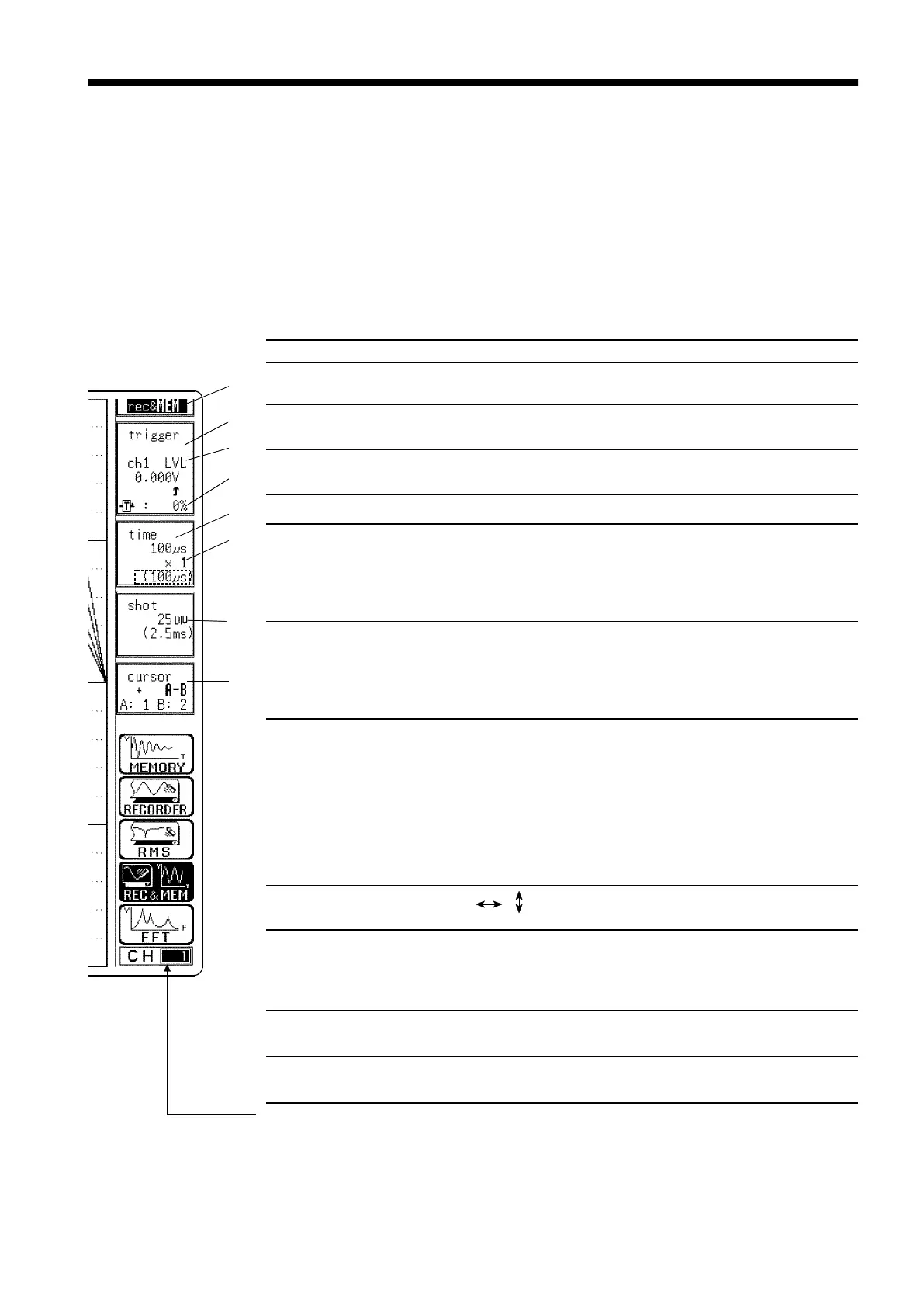
Setting items Selection Explanation
1. Function
MEM, REC, RMS,
REC&MEM, FFT
Select function.
2. Trigger mode
(recorder waveform)
SINGLE, REPEAT,
TIMER
Select trigger mode.
3. Analog trigger
(memory waveform)
OFF, LEVEL, OUT, IN,
V-DROP, CYCLE
Set the analog trigger.
4. Pre-trigger
0 to 100%, -95%
Set the Pre-trigger.
5.
Time Axis Range
20 ms/DIV to
1 h/DIV (REC)
100 μs/DIV to
5min/DIV(MEM)
Set the speed for inputting and
storing the waveform of the input
signal.
Time axis range setting expresses
the time for 1 DIV.
6. Magnification
/compression
along the time axis
×1to×1/500 (REC)
×
10 to
×
1/10000
(MEM)
By magnifying the waveform,
detailed observations can be made.
By compressing the waveform, an
entire change can be promptly
apprehended.
7. Recording Length
SELECT:
25 DIV to continuous
(REC)
25 DIV to 2000 DIV
(MEM)
ARBITRARY:
1 DIV to 1000 DIV
(REC)
1 DIV to 2000 DIV
(MEM)
Using channels: 16 ch
Capacity: 8 M words
The length of recording for one
measurement operation (the number
of DIV) can be set.
8. Cursor
Measurement
OFF, , , +
The A
・
B cursors can be used.
Input channel settings
・ Analog input
・
Logic input
Enables the measurement
conditions for each channel on the
display screen to be set or changed.
See Section 9.10.
Input level monitor
function
Press the
LEVEL MONI
key.
See Section 11.5.
VIEW function
Press the
VIEW
key.
See Section 11.6.
7.4 Settings on the Waveform Display Screen (REC&MEM)
Explains the setting items on the Waveform display screen.
For details on setting, refer to Section 7.3.
When want to use the Jog/Shuttle control, press the
VALUE
select key.
(
The
selection window is not displayed.)
Pressing the F4 function key "REC&MEM" on the Waveform display screen
toggles screen between memory waveform and recorder waveform.
REC&mem
Recorder waveform display in Recorder and Memory function
rec&MEM
Memory waveform display in Recorder and Memory function
Channels that may be changed with the RANGE knob (measurement range)
and POSITION knob (zero position). This channel display is selected with
Channel-select keys CH1 to CH16.
Changing the set channel in the CHANNEL or CH.SET screens modifies the
setting accordingly.