177
────────────────────────────────────────────────────
9.5 Zero Settings
────────────────────────────────────────────────────
9.5.2 Zero Offset Setup
Function
display
Meaning
:
Displays the Zero Offset and Zero Adjust setup
screen.
Function
display Meaning
:
Activates zero offset on all channels.
:
Activates zero offset on specified channels.
:
Disables zero offset on specified channels.
:
Exits Zero setup.
:
Performs zero adjustment.
Disables zero offset on all channels.
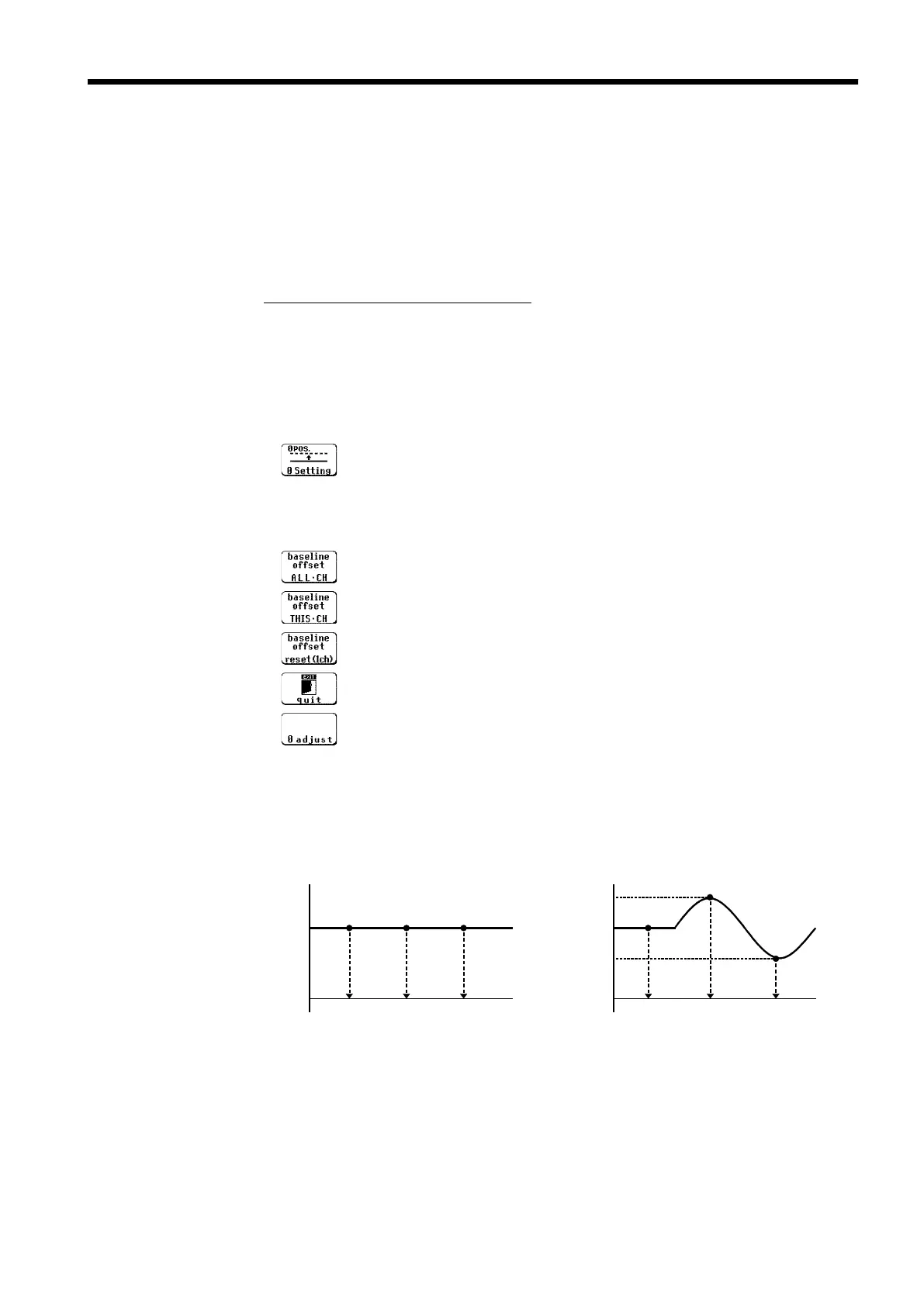
With Fixed Input Voltage With Variable Input Voltage
0V
+V
1
+V1 is set to 0V regardless of timing.
0V
+V
1
The setting value to establish
the 0V level is determined at the
moment of setting.
+V
1
-
V
2
+V
1
+V
2
This function offsets the input voltage measurement to 0 V to compensate
for an actual non-zero input voltage. If the actual input voltage exceeds ±10
divisions, zero offset cannot be performed. This function is for the voltage
and current measurement only.
The zero offset is active when power is off, but if the input unit
configuration is changed while power is on, the zero offset must be reset.
Procedure
Screen: CHANNEL, Waveform display
1. Use the Menu keys to display the desired screen.
2. Move the flashing cursor to the 0 pos. item to be set, and use the function
key to select 0 Setting. (When setting all channels, the channel selection is
irrelevant.)
3. Use the function key to make a setting.
Input Voltage During Zero Offset
To set the zero offset, the input voltage must be stable. Otherwise, the zero
offset depends on the timing of the zero offset setting.