236
────────────────────────────────────────────────────
10.8 Analog Trigger
────────────────────────────────────────────────────
10.8.5 RMS Level Trigger
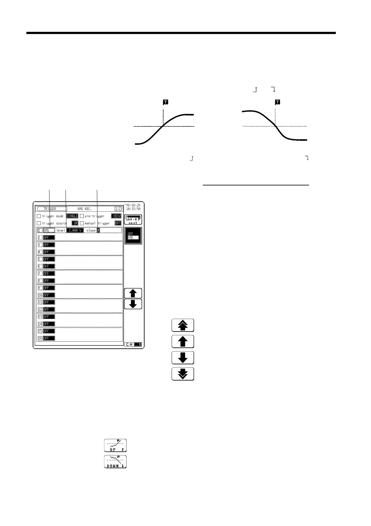
rigger level
RMS value
Trigger level
RMS value
Input signal
Input signal
Trigger point Trigger point
Upward trigger direction (slope : ) Downward trigger direction (slope : )
s885-1
1. 2. 3.
Function
display
Meaning
:
Increases in number, large step
:
Increases in number, small step
:
Decreases in number, small step
:
Decreases in number, large step
Function
display
Meaning
:
Enables triggering on the rising period.
:
Enables triggering on the falling period.
・
The commercial power supplies, 50/60 Hz and the DC signals can be
measured.
・
This trigger occurs when the input signal crosses a predetermined trigger
level (rms value) in a particular direction ("slope": or ).
Procedure
Screen: TRIGGER, Waveform display
(1) Select the RMS level trigger
1. Display the TRIGGER or Waveform display screen.
2. Move the flashing cursor to position
1.
shown in the
figure.
3. Use the function keys to select RMS LEVEL.
(2) Set the trigger level
1. Move the flashing cursor to position
2.
shown in the
figure.
2. Use the Jog/Shuttle control or the function keys to
make the selection.
(3) Select the trigger direction (slope).
1. Move the flashing cursor to position 3. shown in the figure.
2. Use the function keys to select the trigger direction (slope).