165
────────────────────────────────────────────────────
9.1 Overview
────────────────────────────────────────────────────
1
2
3
4
5
6
7
8
9
10
11
12
13
14
15
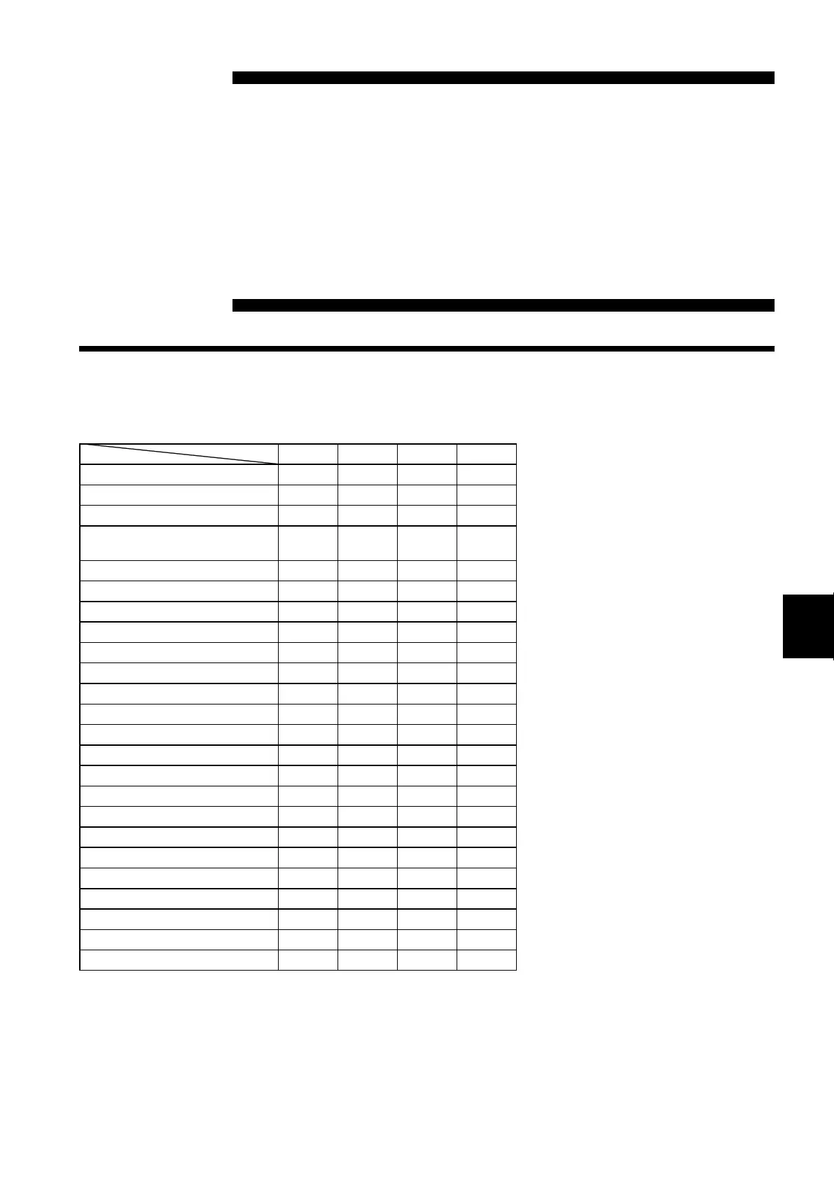
Item Screen Channel Display Status System
Waveform Display Color
● ●
*12
− −
Measurement Range
●
*11
●
*12
− −
Input Coupling
●
*11
●
− −
Magnification/Compression
Ratio Along the Voltage Axis
● ● − −
Zero Position
● ● − −
Zero Adjustment
● ● − −
Zero Offset
*1
● ● − −
Anti-aliasing filter
*2
● ●
*13
− −
Auto Balancing
*3
● ● − −
Digital Filter
*4
● ● − −
Drift Compensation
*5
● ● − −
Hold
*6
● ● − −
Pull-up Resistor
*7
● ● − −
Threshold Value
*8
● − − −
Clamp Check
*9
● − − −
Sensor Sensitivity
*10
● − − −
Low-Pass Filter
● ● − −
Logic Display Color
● ● − −
Logic Display Position
● ● − −
Variable Function
*14
● ● − −
Selecting Functions
● ● ● −
Format
− − ● −
Scaling Function
− − − ●
*11
Comment function
− − − ●
*11
Chapter 9
Input Channel Settings
9.1 Overview
*1: Only voltage and current
measurement
*2: Can be set on the 8938 and 8947
*3: 8939 only
*4: Only voltage measurement on the
8937
*5: Only temperature measurement on
the 8937
*6 Only frequency measurement on
the 8940
*7 Only measurement of frequency,
integration, pulse duty ratio, and
voltage on the 8940
*8: Only measurement of frequency,
integration, and pulse duty ratio
on the 8940
*9: Only current measurement on the
8940
*10: Only measurement of Charge and
Preamp on the 8947
*11: The settings can be copied.
*12: Channels can be set directly on
the Waveform display screen.
*13: Setting is possible on the
Waveform display screen on the
8938.
*14: Only numerical values can be
changed on the display screen.
On/off setting is not possible.