173
────────────────────────────────────────────────────
9.3 Setting the CHA NNEL Screen
────────────────────────────────────────────────────
Single screen format
×
1/2
×
1
×
2
×
5
×
10
2 to 16, X-Y 1,2 screen
format
×
1/4
×
1/2
×
1
×
2.5
×
5
No. of full-scale LSBs
3200 1600 800 320 160
Zero position adjustment area
(MEM, REC, and REC&MEM)
0to100 -50 to 150 -150 to 250 -450 to 550 -950 to 1050
Zero position adjustment area
(RMS)
-50 to 100 -150 to 150 -350 to 250 -950 to 550 -1950 to 1050
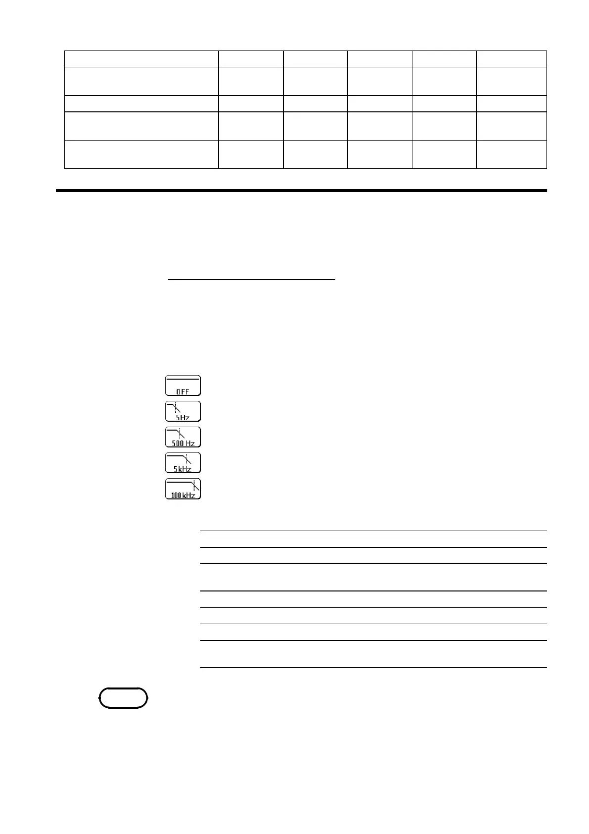
9.3.7 Setting the Low-pass Filter
Function
display
Meaning (When using the 8936 ANALOG UNIT)
:
No low-pass filter is connected.
:
Connect a filter with a cutoff frequency of 5 Hz
:
Connect a filter with a cutoff frequency of 500 Hz
:
Connect a filter with a cutoff frequency of 5 kHz
:
Connect a filter with a cutoff frequency of 100 kHz
Low-pass filter for the units
Unit Low-pass filter [Hz]
8936
OFF,5,500,5k,100k
8937
OFF,5,500,5k,100k(voltage)
OFF, 5, 500 (temperature)
8938
OFF,5,500,5k,100k
8939
OFF, 10, 30, 300, 3 k
8940
OFF,5,500,5k,100k
8947
OFF,5,500,5k,100k(voltage)
OFF, 500, 5 k (acceleration)
NOTE
Low-pass filters internal to the input units are set. Effective for removing
unneeded high-frequency components.
Procedure
Screen: CHANNEL,Waveform display
1. Use the Menu keys to display the desired screen.
2. Press the CH.SET
key to display channel to be set.
3. Move the flashing cursor to the
filter item.
4. Use the function keys to make a setting.
The cutoff frequency of low-pass filter varies depending on the input unit
type.