216
────────────────────────────────────────────────────
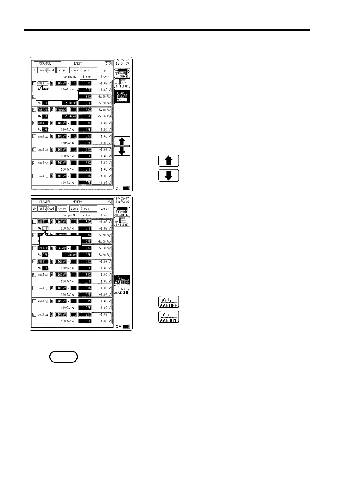
9.15 Setting the 8947 CHARGE UNIT
────────────────────────────────────────────────────
9.15.3 Setting the Voltage Measurement
Flashing cursor
Flashing cursor
Function
display
Meaning
:
Move the cursor up in the selection window.
:
Move the cursor down in the selection window.
Function
display Meaning
:
Anti-aliasing filter is not used.
:
Anti-aliasing filter is used.
NOTE
Procedure
Screen: CHANNEL, Waveform display
(1) Set the measurement mode.
1. Display the CHANNEL or Waveform display screen.
2. Press the CH.SET key and move the flashing cursor to
desired channel.
3. Move the flashing cursor to the unit item.
4. Use the function keys, the Jog/Shuttle control to
select VOLT (voltage).
(2) Set the anti-aliasing filter
Enable the anti-aliasing filter to prevent aliasing
distortion. The cut-off frequency changes automatically
when setting the frequency and time axis ranges. The
anti-aliasing filter can only be selected from the
CHANNEL screen.
1. Move the flashing cursor to the position shown in the
figure on the left.
2. Use the function keys to set.
・
We recommend using an input unit equipped with an anti-aliasing filter that
can be enabled to minimize sampling distortions during FFT analysis.
・
Refer to Appendix 3.10, "FFT Function" for more information about aliasing
distortion and anti-aliasing filters.
・
If the anti-aliasing filter is on, "A" is printed at the end of the filter settings
page during list printing. Refer to Section 13.5, "Example of Printer Output".
・
Refer to Section 8.3.3, "Setting the Frequency Range" for details about the
relationship between the anti-aliasing filter cutoff frequency and the
frequency range and time axis range.