379
────────────────────────────────────────────────────
17.1 External Input/Output Terminals
────────────────────────────────────────────────────
16
17
18
19
5
6
7
8
9
10
11
12
13
14
A
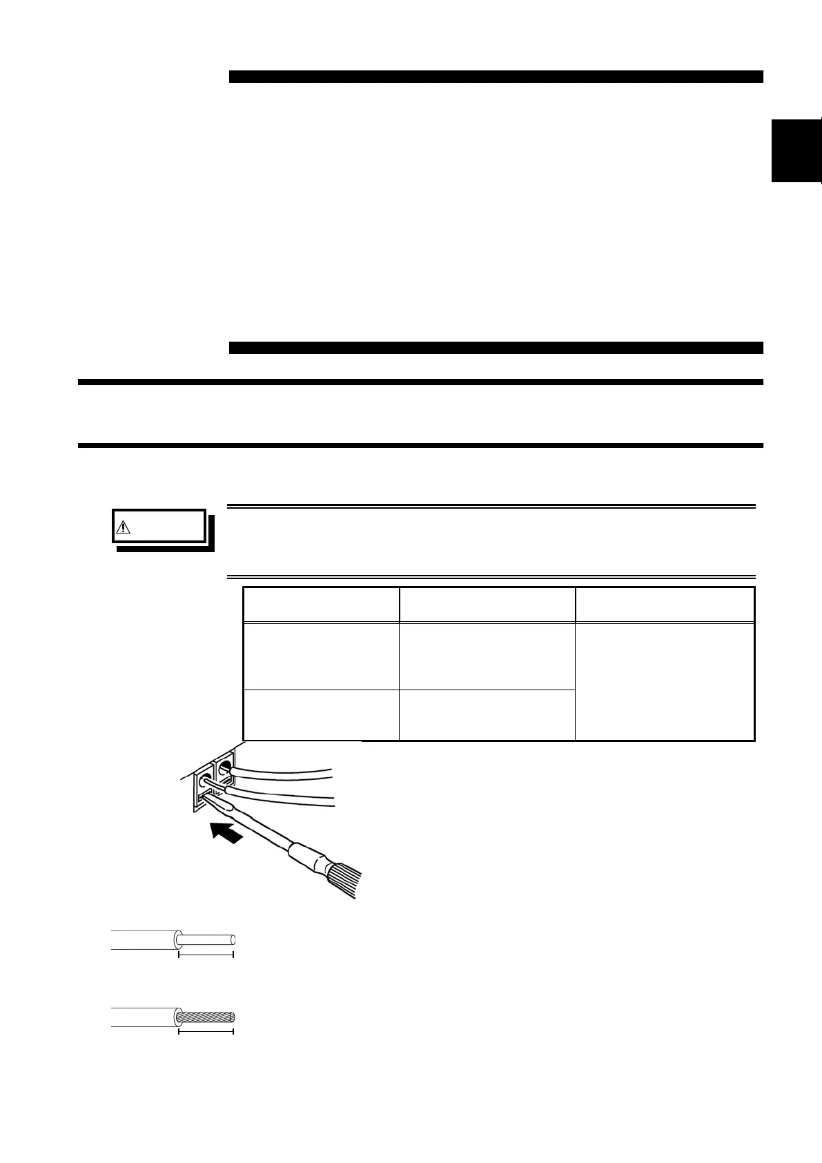
17.1.1 Connecting the Terminals
WARNING
Maximum input voltage ratings for the input/output terminals of the
8841/42 are shown below. To avoid the risk of electric shock and
damage to the unit, take care not to exceed these ratings.
Input/output terminal Maximum input voltage
Maximum rated voltage
to earth
EXT TRIG
START・STOP
PRINT
EXT SMPL
-5 to +10 VDC
Not insulated
TRIG OUT
GO
NG
-20 V to +30 VDC
500 mA max.
200 mW max.
10 mm
Single strand
Multi-strand
1.0 mm dia.
(0.3 to 1.0 mm dia
can be used .
0.75 mm
2
(0.3 to 0.75 mm
2
can be used )
Diameter per strand:
minimum 0.18 mm dia.
10 mm
Chapter 17
External Input/ Output Terminals/
Key Lock Function
17.1 External Input/Output Terminals
1. Push the tab with a flatblade screwdriver or similar.
2. While keeping the tab depressed, insert a stripped wire
into the connector opening.
3. Release the tab to lock the wire.
Recommended wire
Single strand: 1.0 mm dia. (AWG #18)
Multi-strand: 0.75 mm
2
Usable limits
Single strand: 0.3 to 1.0 mm dia. (AWG #26 to #18)
Multi-strand: 0.3 to 0.75 mm
2
(AWG #22 to #20)
Strand diameter: minimum 0.18 mm
Standard insulation stripping length: 10 mm