247
────────────────────────────────────────────────────
11.2 Using the A
・
BCursors
────────────────────────────────────────────────────
1
2
3
4
5
6
7
8
9
10
11
12
13
14
15
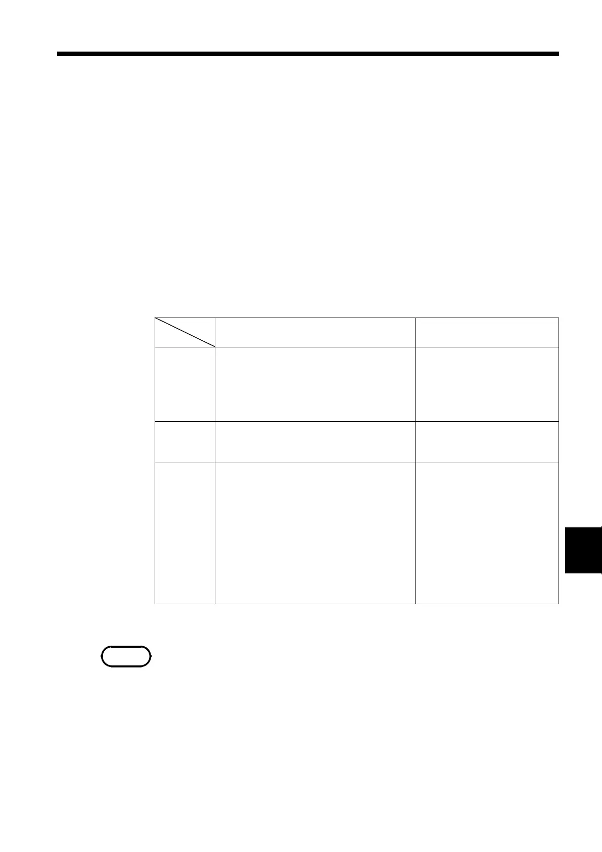
Cursor
Value
AorB B-A
Vertical
t Time from the trigger point (MEM,
RMS, memory waveform in
REC&MEM)
Time from recording start (REC,
recorder waveform in REC&MEM)
1/t Frequency taking t as the period
t Time interval between
the A and B cursors
1/t Frequency taking t as
the period
Horizontal
v Voltage value for channel selected v Potential difference
between the A and B
cursors.
Trace
t Time from trigger point (MEM,
RMS, FFT, memory waveform in
REC&MEM)
Time from recording start (REC,
recorder waveform in REC&MEM)
v Voltage value for channel selected
(MEM, FFT, memory waveform in
REC&MEM)
Maximum and minimum values for
channel selected (REC, RMS,
recorder waveform in REC&MEM)
f Analysis frequency (FFT)
t Time difference between
the trace points
v Potential difference
between the trace points
f Frequency difference
between the trace points
(FFT)
NOTE
11.2 Using the A・B Cursors
The A・B cursors can be used to read a time difference, frequency, or
potential difference on screen. (When scaling is used, the difference is
displayed in the scaling value. See Section 9.8.)
Line Cursor (vertical, horizontal)
The value at cursor A and cursor B, and the value between the two cursors
can be determined.
Trace Cursor
・ Memory recorder, memory waveform in REC&MEM, FFT
The value at the point where the cursor crosses the waveform can be
determined. The trace point moves on the waveform of the specified channel.
・ Recorder, RMS recorder, recorder waveform in REC&MEM
The intersection between the cursor and the waveform is displayed midway
between of the maximum and minimum values.
MEM: memory recorder function, REC: recorder function, RMS: rms
recorder function
・ When the time-axis range of the RMS recorder is 5 s/division, the trace
cursor value of "v" is the voltage value of the selected channel.
・ When external sampling is being performed, a "t" is included in the
sampling number.
・ While the settings are made on the Waveform display screen (displaying the
input channel), the value between A and B cursors is no displayed.
・ A・B cursor measurements are enabled even if the line cursor (vertical) or
trace cursor are off the screen. When the cursor is set to A&B and either the
A or B cursor is moved, both A and B cursors are shifted onto the screen.