252
────────────────────────────────────────────────────
11.2 Using the A
・
BCursors
────────────────────────────────────────────────────
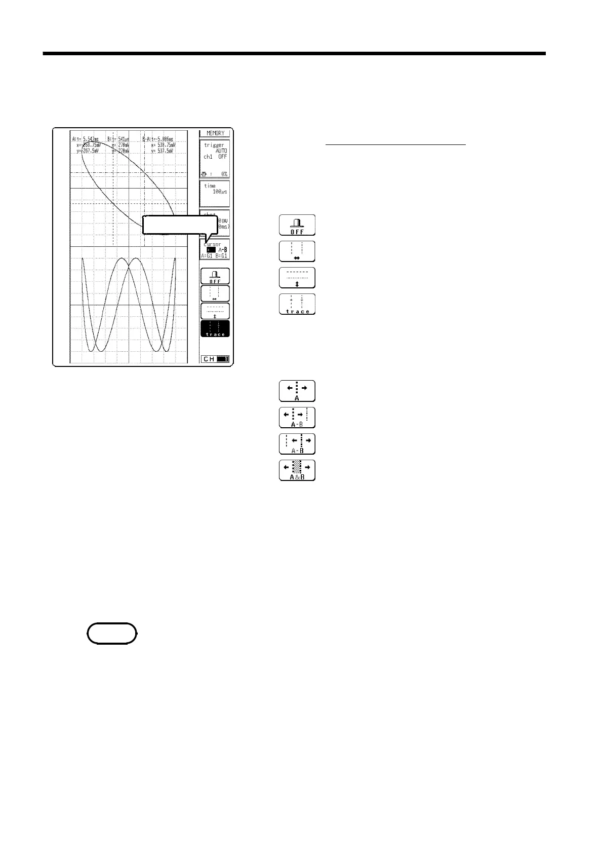
11.2.4 Using the A
・
B Cursors (X-Y Screen)
Flashing cursor
Function
display
Meaning
#9-1 ##g-cur3
:
Disable A・Bcursors
:
Line cursor (vertical: t, 1/t)
:
Line cursor (horizontal: v)
:
Trace cursor (the point where the cursor
crosses the waveform)
Function
display Meaning
#9-2
:
Use A cursor only
:
Move the A cursor only
:
Move the B cursor only
:
MoveboththeAandBcursors
NOTE
The cursor can be used on the X-Y screen. Partial X-Y plotting enables
operation of the A
・
B cursors.
Procedure
Screen: X-Y Waveform display
1. Move the flashing cursor to the
cursor
item
2. Use the function keys to make selection.
3. Use the function keys to select the cursor to be
moved.
4. The graph setup menu appears below the cursor.
Using the function keys or the Jog/Shuttle control,
move the flashing cursor to set the graph of the
waveform for which the voltage is to be read. This
channel setting must be performed for both cursors A
and B.
5. Press the A
・
B CSR select key.
6. Rotate the Jog/Shuttle control to move the cursor.
By specifying a different graph for the A and B cursors, a potential
difference between the waveforms in the respective channels can be
determined.