382
────────────────────────────────────────────────────
17.1 External Input/Output Terminals
────────────────────────────────────────────────────
17.1.6 GO/NG Evaluation Output Terminal
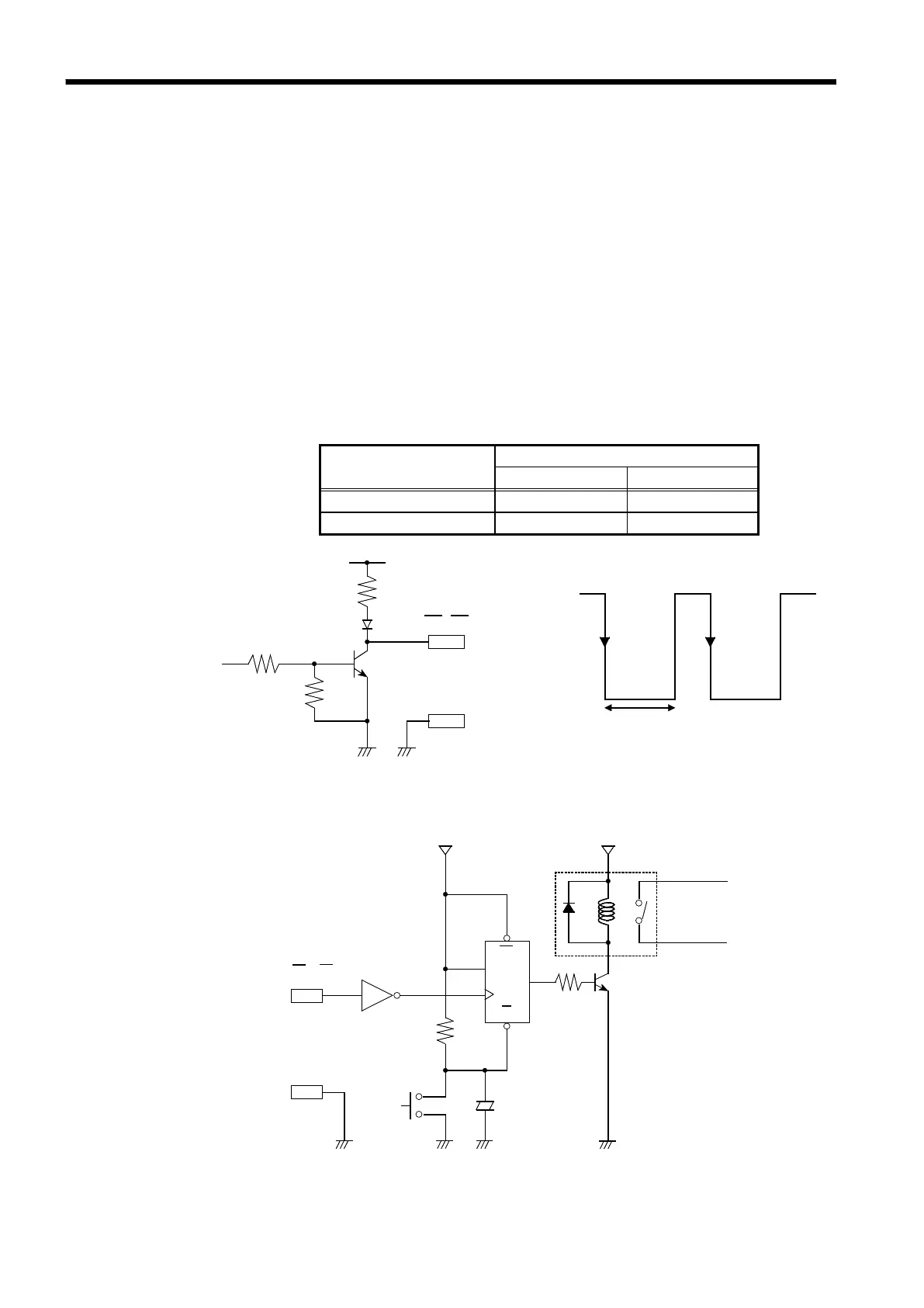
Output Terminal
Evaluation result
GO NG
GO Low level High level
NG High level Low level
4.0 to 5.0V
0to0.5V
Evaluation output interval
1μF
1to5kΩ
Output
elay
Q
HC04
R
When waveform evaluation or waveform parameter evaluation is used, a
signal is output from these connectors when the result is GO (pass) or NG
(fail).
Output signal
Signal type Open-collector signal, active Low
Output voltage range High level: 4.0 to 5.0 V, Low level: 0 to 0.5 V
Maximum input voltage -20 to +30 V, max. 500 mA, max. 200 mW
Evaluation output interval (min. 70 ms)
The evaluation outputs are shown in the following table. Between these
states, there is an interval during which the next data are read and waveform
data are created. The duration of this interval is inversely proportional to the
time axis and proportional to the recording length.
The following diagram shows an example of a circuit that operates an alarm
by means of a GO/NG terminal.