217
────────────────────────────────────────────────────
10.1 Overview of the Trigger Functions
────────────────────────────────────────────────────
1
2
3
4
5
6
7
8
9
10
11
12
13
14
A
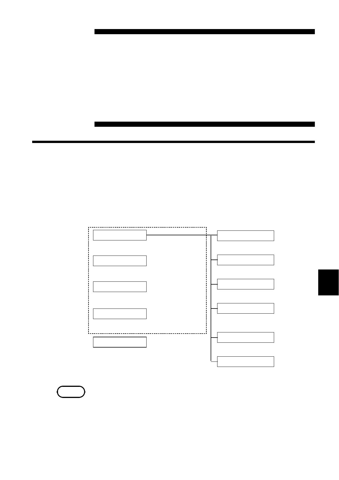
Analog trigger
Logic trigger
External trigger
Timer trigger
The input signal to analog units
CH1 to CH16
is used as tri
er source.
The input signal to logic channels
CHA to CHD
is used as tri
er source
The input signal to the EXT TRIG
connectors used as tri
er source.
Triggering occurs from a preset start time
to a
reset sto
time.
Manual trigger
Triggering occurs when the MANU TRIG key
is pressed.
When the input signal crosses
the tri
er level.
When the input signal enters
the s
ecified ran
e.
When the input signal leaves
the s
ecified ran
e.
hen the commercial power
supply voltage fall slower than
the settin
level.
When the signal goes out of
a
reset
eriod ran
e.
When the input signal crosses
a
reset level
rms value
.
Level trigger
Window-in trigger
Window-out trigger
Voltage drop trigger
Period trigger
RMS level trigger
NOTE
Chapter 10
Trigger Functions
10.1 Overview of the Trigger Functions
・
The term "trigger" refers to a signal which is used to control the timing for
recording start or stop.
・
The term "triggering has occurred" refers to the state when such a signal has
activated recording start or stop.
・
Trigger parameters for the various functions are set using the TRIGGER
screen or the Waveform display screen.
・
The manual trigger is always activated when the MANU TRIG
key is pressed,
regardless of other trigger source settings.
・
If the trigger settings (trigger source parameters, pre-trigger) are changed
during recording, the measurement is restarted, using the new settings.