174
────────────────────────────────────────────────────
9.3 Setting the CHA NNEL Screen
────────────────────────────────────────────────────
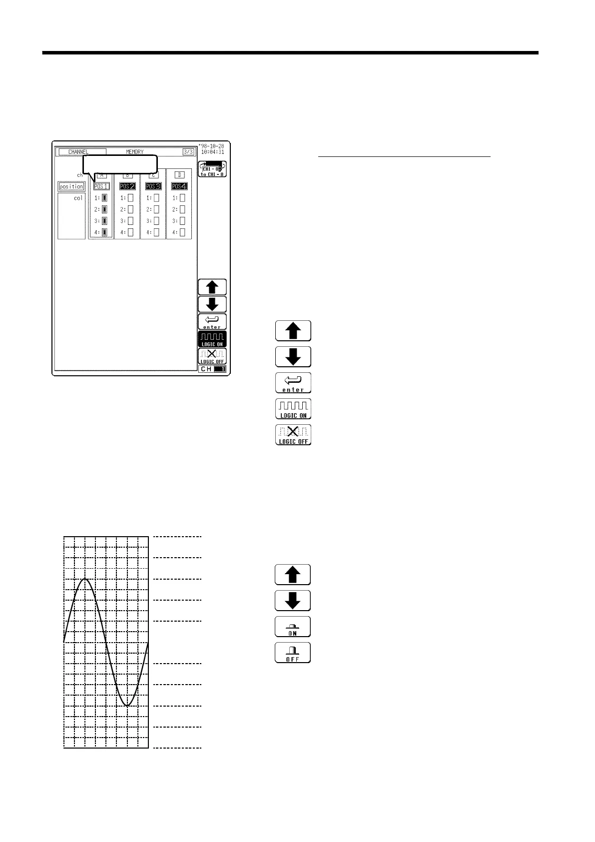
9.3.8 Setting the Logic Inputs
s7311
Flashing cursor
Function
display Meaning
g-ent,LOG1, 2
:
Change the display position.
:
Change the display position.
:
Set to the displayed position number.
:
All logic waveforms are displayed.
:
Logic waveforms are not displayed.
Position 1
4
5
6
7
8
2
3
The logic waveform display
positions are as follows.
Function
display Meaning
##F2
:
Move the cursor up in the selection window.
:
Move the cursor down in the selection window.
:
Waveform is performed.
:
Waveform is not performed.
・Select the display positions for CHA - CHD (1 probe).
・Select the display color for the logic waveform.
Procedure
Screen: CHANNEL, Waveform display
1. Use the Menu keys to display the desired screen.
Then press the CH.SET
key to display the logic
channel setting screen.
2. Move the flashing cursor to the
Position point of the
channel to be set, as shown in the figure on the left.
3. Use the function keys to set the position.
4. Select the enter function key or move the flashing
cursor to change the display position.
5. Move the flashing cursor to the "1" to "4" item of the
channel for which the display color is to be set.
6. Use the the function keys to make the selection.