290
────────────────────────────────────────────────────
13.4 Setting the SYSTEM Screen (printout)
────────────────────────────────────────────────────
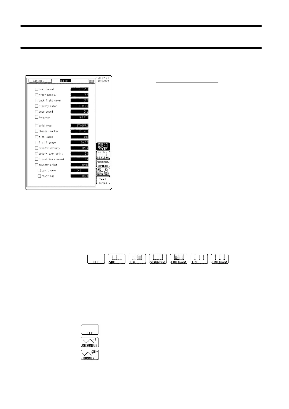
13.4.1 SET UP Screen (SYSTEM 1)
s1141
Grid Type
gc-grid1, 2, 3,
4
5
6
Channel Marker
Function
display
Meaning
gc-CHA1,2
:
Channel numbers will not be printed for the
waveform on the recording paper.
:
Channel numbers will be printed for the
waveform on the recording paper.
:
Comments will be printed for the waveform on
the recording paper.
13.4 Setting the SYSTEM Screen (printout)
Procedure
Screen: SETUP (SYSTEM1)
1. Press the
SYSTEM
key to display the SET UP screen.
2. Move the flashing cursor to desired item.
3. Use the function keys to make the selection.
For details, see Section 13.5.
In FFT function, the setting of the channel marker, time
axis display, upper and lower limits of printing, zero
position comment, and counter printing cannot be made.
・Selects the type of grid shown on the Waveform display screen and drawn on
the recording paper.
・On the waveform display screen, the standard and fine grids are defined as
the standard, and the standard (dark) and fine (dark) grids are defined as the
standard (dark) grids.
・"Time" and "Time (dark)" can be set only during printing.
In printing in the X-Y screen format or FFT function, the standard time axis
and the standard time axis (dark) are applied.
The channel numbers or the comments are printed together with the
waveform on the recording paper.
Comments can be set on SYSTEM3 (COMMENT) screen.