170
────────────────────────────────────────────────────
9.3 Setting the CHA NNEL Screen
────────────────────────────────────────────────────
9.3.3 Setting the Voltage Axis Range
Function
display
Meaning
:
Move the cursor up in the selection window.
:
Move the cursor down in the selection window.
NOTE
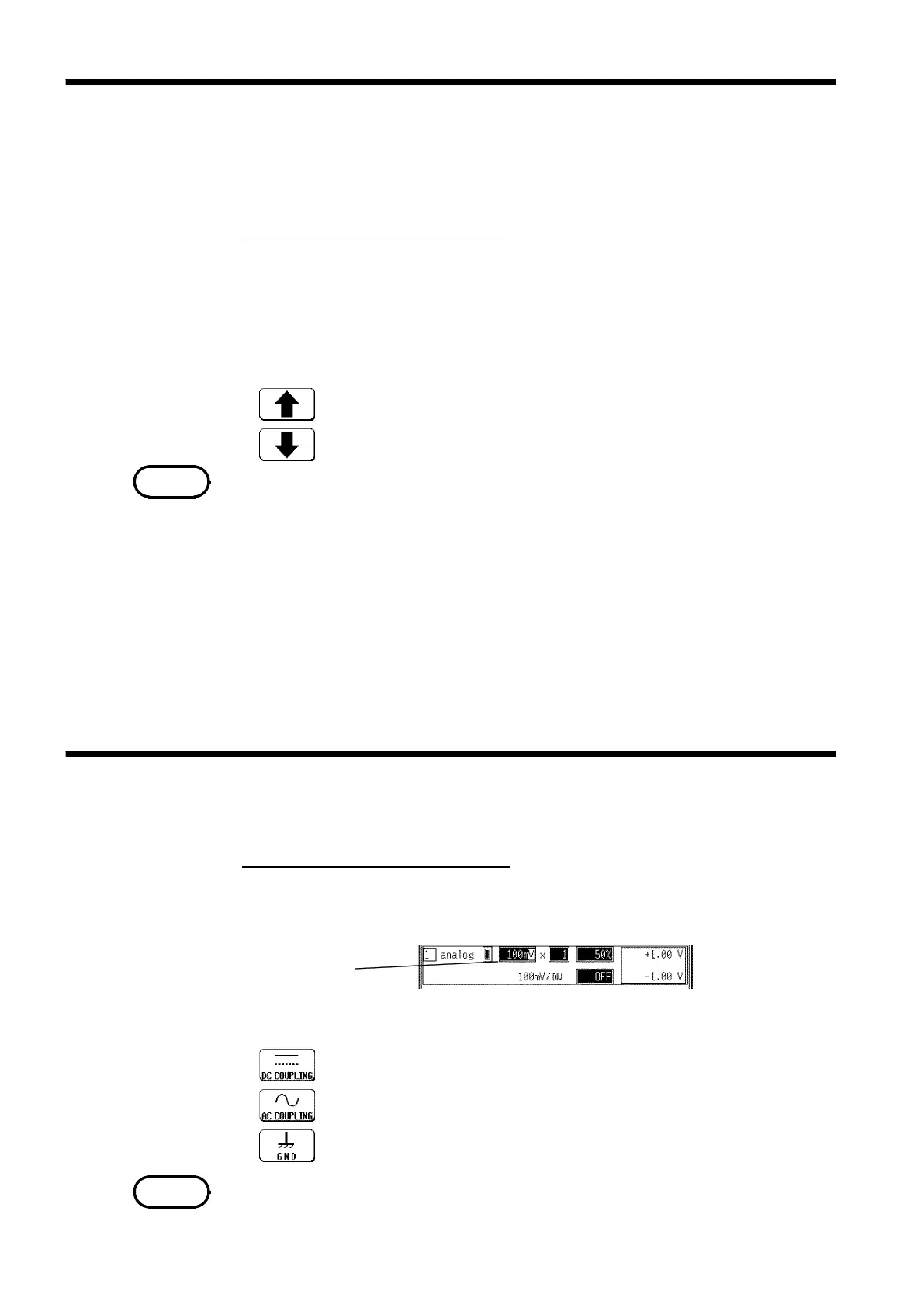
9.3.4 Setting the Input Coupling
Flashing cursor
Function
display Meaning
:
DC coupling
:
AC coupling
:
The input signal is not connected. This allows
the zero position to be checked.
NOTE
・The measurement range for each channel is set.
・The set value denotes the voltage value for 1 DIV along the measurement
range (vertically).
Procedure
Screen: CHANNEL,Waveform display
1. Use the Menu keys to display the desired screen.
2. Press the CH.SET key to display channel to be set.
3. Move the flashing cursor to range item.
4. Use the function keys, Jog/Shuttle control, or RANGE knob to make a setting.
・ The RANGE knob can be used regardless of where the flashing cursor is
located.
・ If the variable function is enabled, the size of a waveform on the screen does
not change, even if the measurement range is changed.
・ The symbol "*" in the selection window indicates the time axis of the data
stored to current memory. (If no data is present in memory, this symbol is
not displayed.)
・ When the waveform is out of range, the color of the displayed waveform on
the screen is changed.
・ When using the RMS recorder function, you cannot set the lowest sensitivity
range of each unit (20 V/DIV for the 8936).
The input coupling for the input signal is set.
Procedure
Screen: CHANNEL, Waveform display
1. Use the Menu keys to display the desired screen.
2. Press the CH.SET key to display channel to be set.
3. Move the flashing cursor to the position as shown in the figure below.
4. Use the function keys to make a setting.
It is not possible to select AC couplings for the 8946.