211
────────────────────────────────────────────────────
9.14 8940 F/V UNIT
────────────────────────────────────────────────────
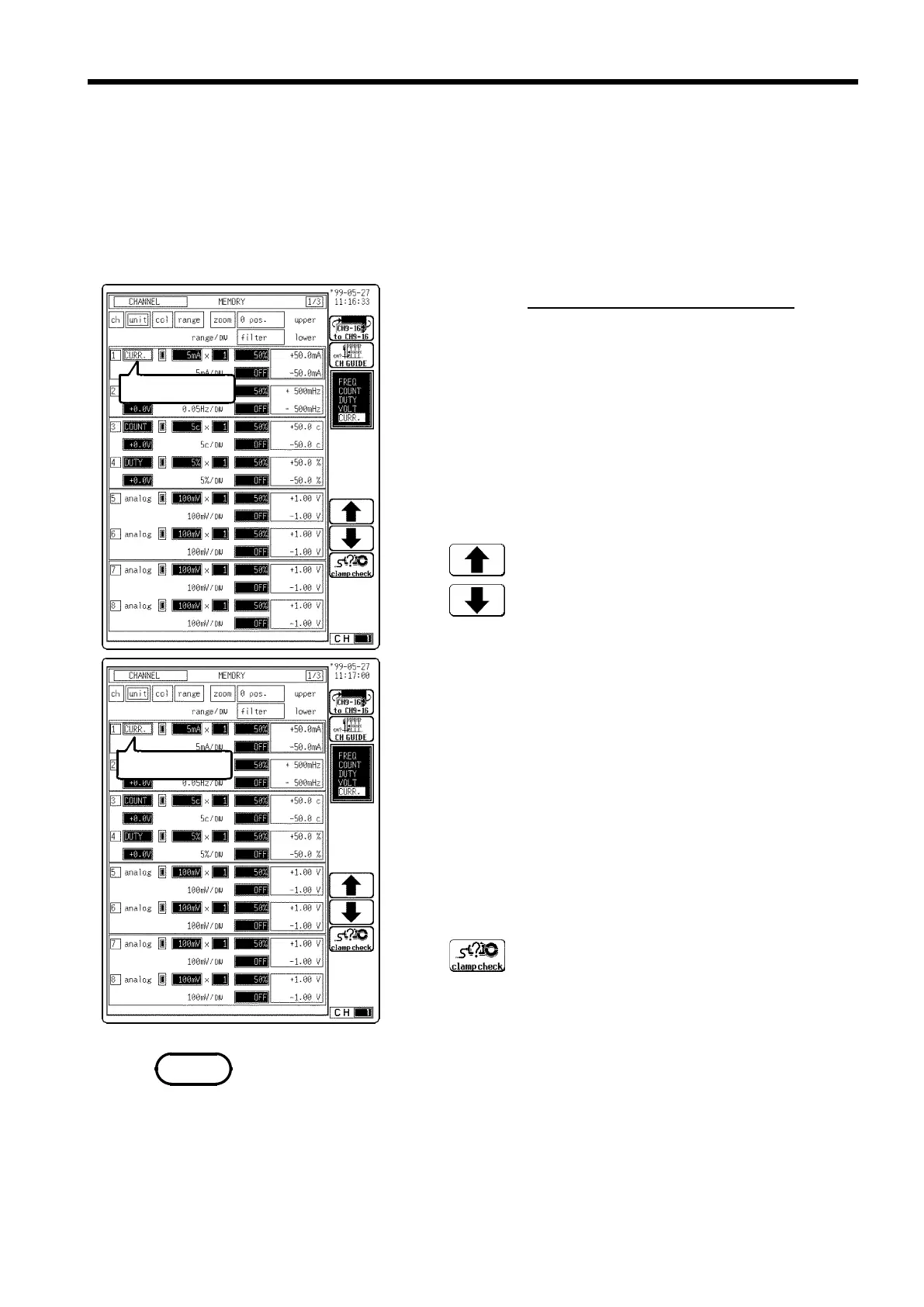
9.14.5 Setting the Current Measurement
Flashing cursor
Flashing cursor
Function
display
Meaning
:
Move the cursor up in the selection window.
:
Move the cursor down in the selection window.
Function
display
Meaning
:
Clamp check is carried out.
NOTE
Current measurement is possible by connecting a clamp-on sensor/probe
using the Model 9318 or 9319 CONVERSION CABLE. The following table
shows which Cable to use with each sensor/probe model. Refer to Section
2.4.4 for connection methods.
9318: 9270, 9271, 9272, 9277, 9278, 9279
9319: 3273
Procedure
Screen: CHANNEL, Waveform display
(1) Set the measurement mode.
1. Display the CHANNEL or Waveform display screen.
2. Press the CH.SET key and move the flashing cursor to
desired channel.
3. Move the flashing cursor to the unit item.
4. Use the function keys, the Jog/Shuttle control to
select CURR. (current).
(2) Execute the clamp check.
The clamp check identifies the clamp sensor (probe) for
use. It must be performed before current measurement.
Up to 4 channels can be selected for current
measurement at the same time on the 8841/42.
1. Move the flashing cursor to the position shown in the
figure on the left.
2. Connect the clamp sensor and select clamp check by
using the function keys.
Up to four channels can be selected for current measurement at the same
time on the 8841/42. However, the clamp check does not work correctly
when more than four clamps are installed. Remove any extra clamps so that
no more than four are installed before attempting the clamp check.