210
────────────────────────────────────────────────────
9.14 8940 F/V UNIT
────────────────────────────────────────────────────
Flashing cursor
Flashing cursor
Function
display
Meaning
:
DC coupling
:
AC coupling
:
The input signal is not connected.
Function
display Meaning
:
Pull-up resistance is enabled (ON).
(for connection to open collector output)
:
Pull-up resistance is disabled (OFF).
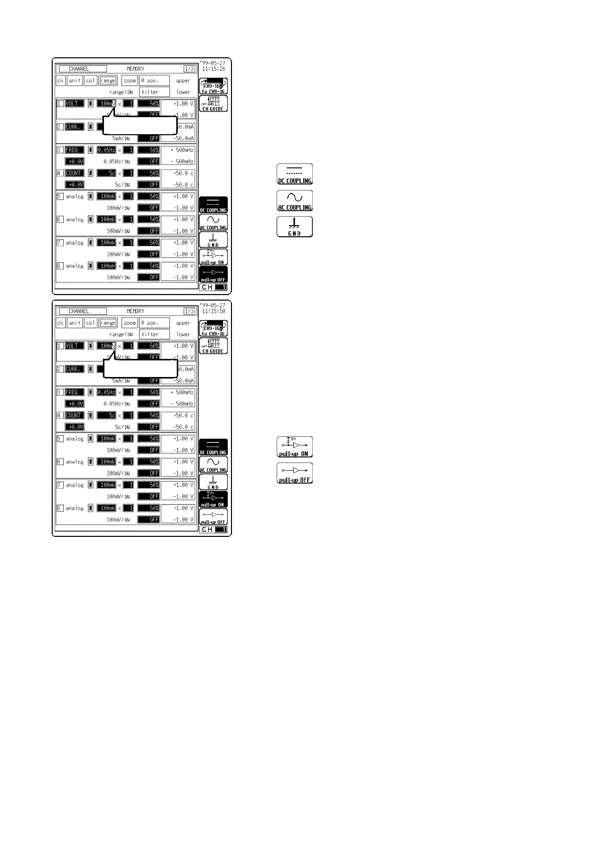
(3) Set the input coupling.
1. Move the flashing cursor to the position shown in the
figure on the left.
2. Use the function keys or Jog/Shuttle control to select
the input coupling.
(4) Set the pull-up resistance.
Set the pull-up resistance on or off. Pull-up resistance
is used when connecting to an open collector output
signal. For normal measurements, disable the pull-up
resistance (set to OFF).
1. Move the flashing cursor to the position shown in the
figure on the left.
2. Use the function keys to make a setting.