188
────────────────────────────────────────────────────
9.9 Comment Function (SYSTEM 3)
────────────────────────────────────────────────────
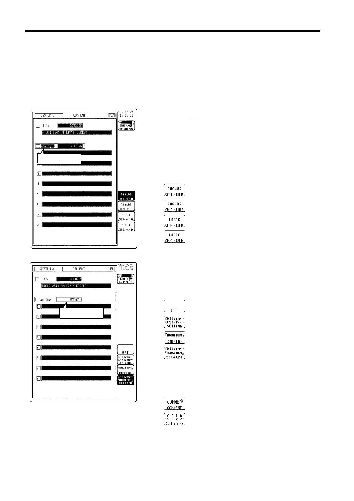
9.9.2 Analog/Logic Channel Comment Entry
s762-1, 2
Flashing cursor
Flashing cursor
Function
display Meaning
:
Analog channels 1 to 8
:
Analog channels 9 to 16
:
Logic channels A and B
:
Logic channels C and D
Function
display
Meaning
:
Standard printout is performed.
:
Setting item is printed.
:
Comment is printed.
:
Both item and comment are printed.
Function
display
Meaning
:
Input comment.
:
Clear comment.
Comments of up to 40 characters can be included on the recording paper on
each channel. If "COMMENT" or "SET & COM" is
selected,
this comment
will be included on the recording paper in all functions.
"SET & COM" prints the settings for each channel (voltage axis range,
magnification of voltage axis, zero position, low-pass filter, and full span
voltage range), along with comments.
Procedure
Screen: COMMENT (SYSTEM3)
1. Press the SYSTEM key to display the comment setting
screen.
2. Move the flashing cursor to the position shown in the
figure on the left, and use the function keys to select
the desired channel screen.
3. Move the flashing cursor to the position shown in the
figure on the left.
Use the function keys to make the selection.
4. Move the flashing cursor to the channel to be input
and use the function keys to make the selection.
For details on comment input, see Section 9.9.3, and for
the example of printing, see Section 13.5.