95
────────────────────────────────────────────────────
6.4 Settings on the Waveform Display Screen (RMS)
────────────────────────────────────────────────────
1.
2.
3.
4.
5.
6.
7.
8.
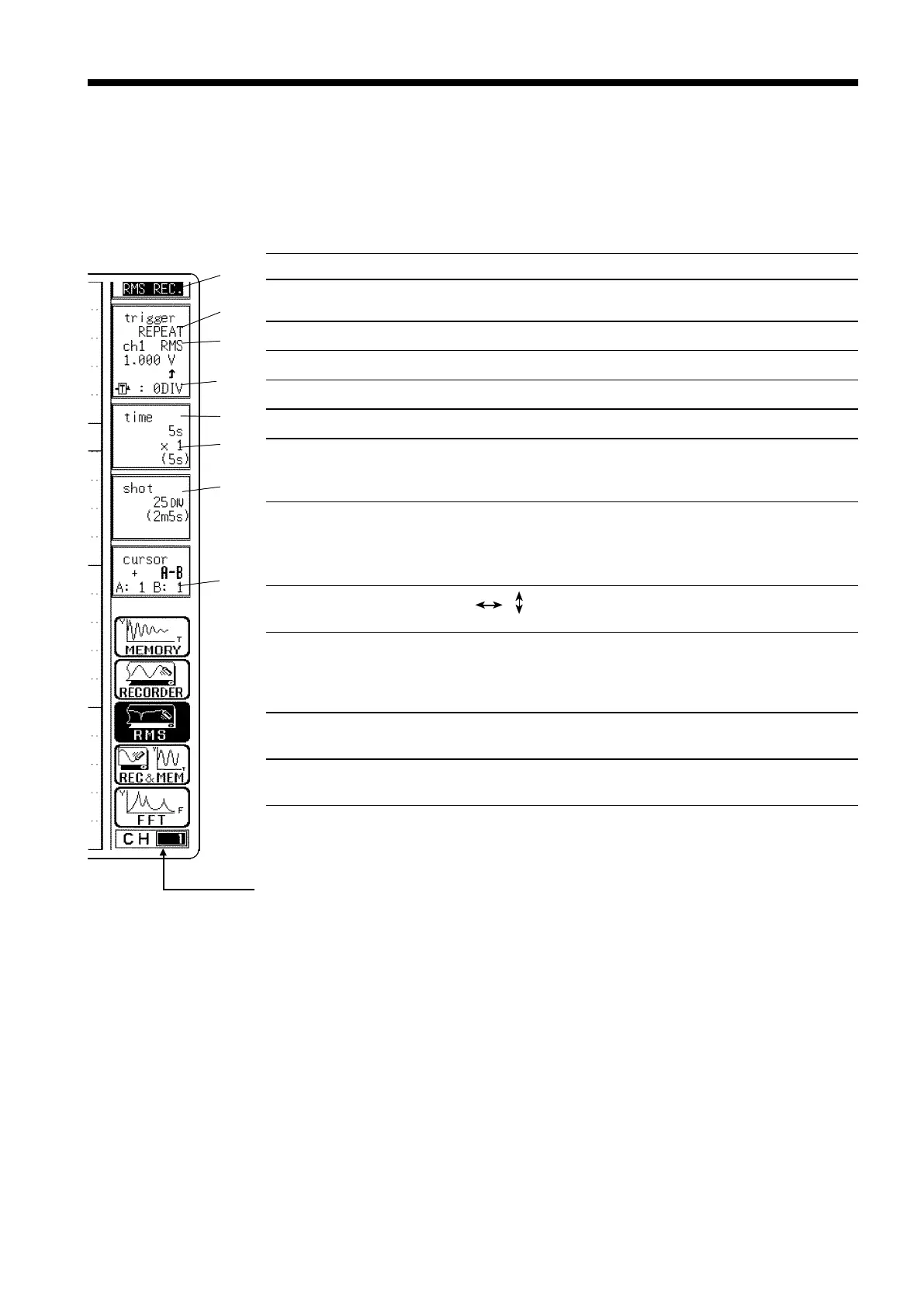
Setting items Selection Explanation
1. Function
MEM, REC, RMS,
REC&MEM, FFT
Select function.
2. Trigger mode
SINGLE, REPEAT
Select trigger mode.
3. Analog trigger
RMS LEVEL
Set the analog trigger.
4. Pre-trigger
0, 5, 10 DIV
Set the Pre-trigger.
5. Time axis
5 s/DIV to 1 h/DIV
Set the time 1 scale (1 DIV).
6. Compression along
the time axis
×1to×1/500
By compressing the waveform, an
entire change can be promptly
apprehended.
7. Recording length
(Capacity
:
8M
words)
SELECT: 25 DIV to
CONT
ARBITRARY: 1 DIV to
2000 DIV
The length of recording for one
measurement operation (the number
of DIV) can be set.
8. Cursor
Measurement
OFF, , ,
+
The A
・
B cursors can be used.
Input channel settings
・Analog input
・
Logic input
・X, Y axis
(X-Y format)
Enables the measurement
conditions for each channel on the
display screen to be set or changed.
See Section 9.10.
Input level monitor
function
Press the
LEVEL MONI
key.
See Section 11.5.
VIEW function
Press the
VIEW
key.
See Section 11.6.
6.4 Settings on the Waveform Display Screen (RMS)
Explains the setting items on the Waveform display screen.
For details on setting, refer to Section 6.3.
When want to use the Jog/Shuttle control, press the
VALUE
select key.
(
The
selection window is not displayed
s64
Channels that may be changed with the RANGE knob (measurement range)
and POSITION knob (zero position).This channel display is selected with
Channel-select keys CH1 to CH16.
Changing the set channel in the CHANNEL or CH.SET screens modifies the
setting accordingly.