380
────────────────────────────────────────────────────
17.1 External Input/Output Terminals
────────────────────────────────────────────────────
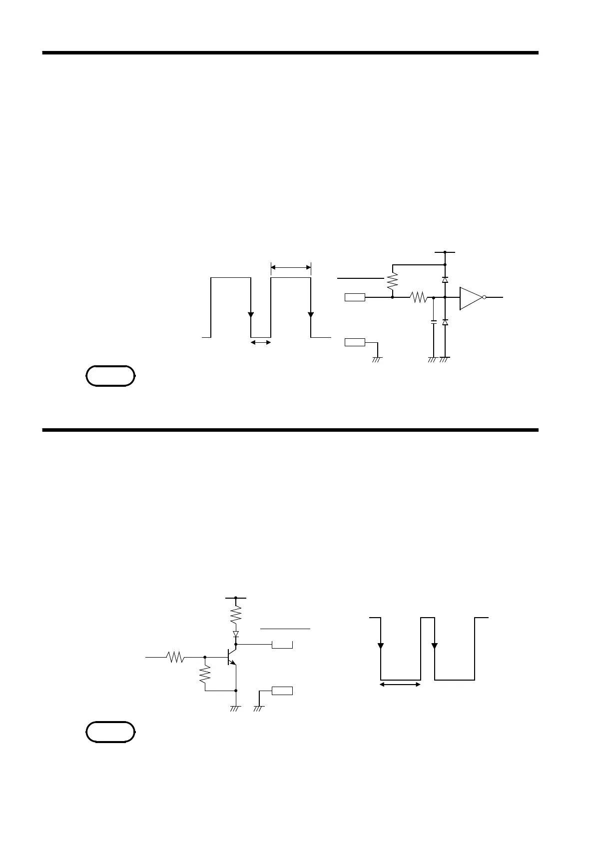
17.1.2 External Trigger Input Terminal [EXT TRIG]
3.3 kΩ
5V
470 Ω
2200
F
GND
EXT TRIG
HIGH
2.5 to 5.0V
LOW
0to1.0V
2μsmin.
1msmin.
NOTE
17.1.3 Trigger Output Terminal [TRIG OUT]
10 kΩ
5V
TRIG.OUT
4.7 kΩ
4.7 kΩ
HIGH
4.0 to 5.0V
LOW
0to0.5V
10 ms min.
GND
NOTE
・
An external signal can be used as trigger source.
・
Several 8841/42 units can be synchronized for parallel operation.
Signal input method
・
Short the terminal to ground, or input a pulse signal (High level: 2.5 to 5.0
V, Low level: 0 to 1.0 V) or a square wave signal.
・
Triggering is activated at the falling edge of 2.5 V of the input waveform or
using a terminal short.
Voltage range High level: 2.5 to 5.0 V, Low level: 0 to 1.0 V
Pulse width High level: min. 1 ms, Low level: min. 2μs
Maximum input voltage -5 to 10 V
The external trigger input (EXT TRIG) cannot be used, unless the external
trigger is enabled on the TRIGGER screen.
・When triggering occurs, a signal is output from this terminal.
・Several 8841/42 units can be synchronized for parallel operation.
Trigger output signal
Signal type Open-collector signal, active Low
Output voltage High level: 4.0 to 5.0 V
range Low level: 0 to 0.5 V
Pulse width Low level:min. 10 ms.
Maximum input voltage -20 to +30 V, max. 500 mA, max. 200 mW
When the auto range function is activated by pressing the
AUTO
key, a trigger
output signal is generated. This should be taken into consideration when
using both the trigger output and the auto range function. (Memory recorder
function only)