401
────────────────────────────────────────────────────
19.1 Logic Inputs
────────────────────────────────────────────────────
16
17
18
19
5
6
7
8
9
10
11
12
13
14
A
WARNING
The unit has separate inputs for four probes, but the ground lines of
these inputs are not isolated from each other and from the frame
ground of the unit (common ground). If voltage having a different
ground level is input, a short circuit will occur, depending on the
probe type.
Do not connect logic probes other than supplied by HIOKI to the
logic inputs.
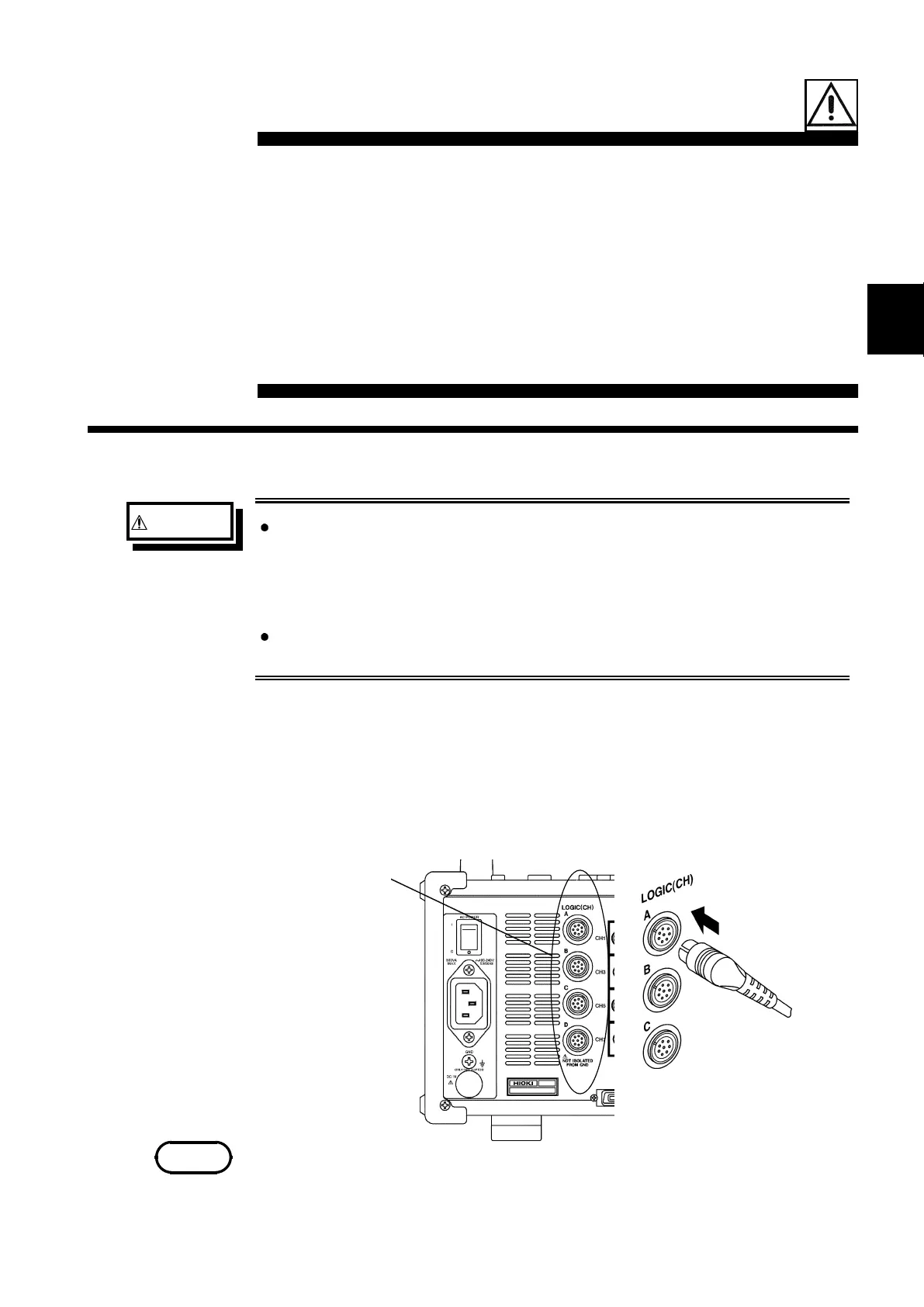
Logic input
NOTE
Chapter 19
Logic and Analog Inputs
19.1 Logic Inputs
Logic Probe Connection
・The logic input is located on the right side of the unit. Up to four probes
can be connected.
・Since one logic probe can record 4 channels, the combined maximum
recording capability for logic waveforms is 16 channels.
・Connect the probe by aligning the groove on the plug with the ridge on
the connector.
・If no logic probe is connected, the corresponding logic waveform is
displayed on the screen at high level.
・Carefully read the instruction manual supplied with the probe.